Faux Concrete vs Rammed Earth Wall Panels: MCM Spec Guide
Updated
Approving a small crop can leave unexpected joints or interrupted strata. Choose faux concrete wall panels for a cement-grey composition, or rammed-earth-look MCM panels for layered mineral bands. This spec guide compares five decorative modified-clay/mineral-composite (MCM) wall finishes for dry interiors; approve adjoining sheets under the intended light before ordering.
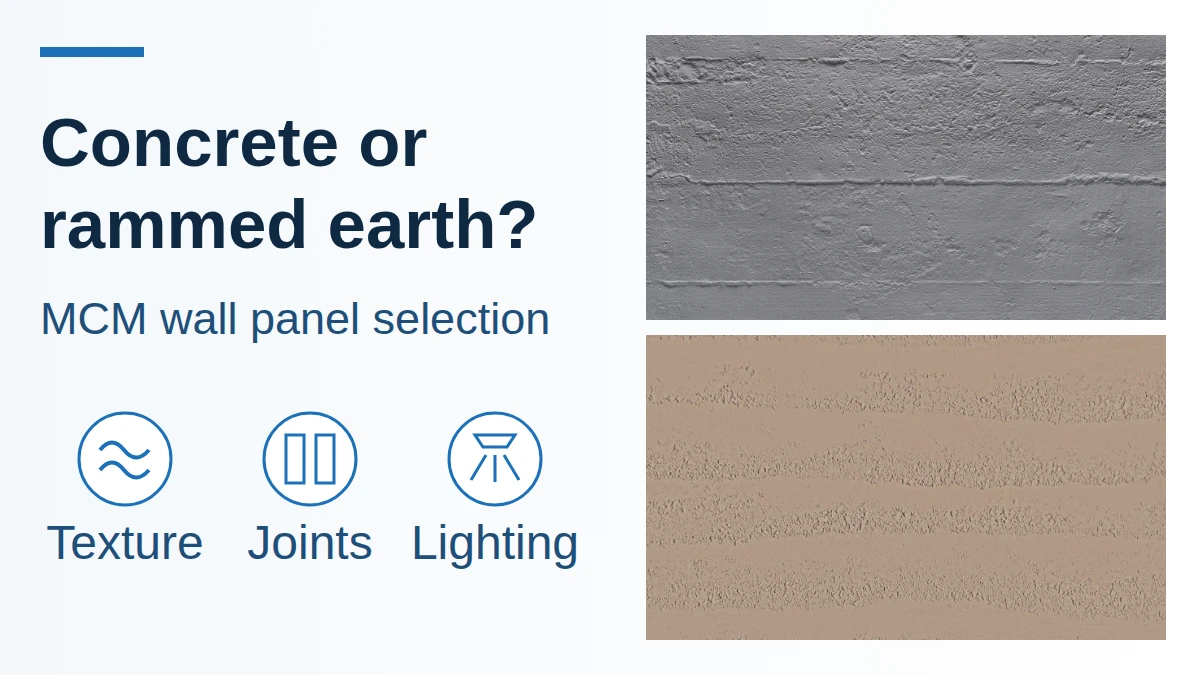
Set the wall brief before selecting a finish
Start with the intended composition: broad cast marks, regular board-like lines or layered earth bands. Then check the actual sample at the closest occupied position and along the normal approach to the wall. Approve the texture, the sheet sequence and the lighting as one wall composition. A photograph helps shortlist finishes; the physical layout establishes which variation, joint visibility and shadow pattern the project will accept.
| Input or item | Typical value or source | Why it matters |
|---|---|---|
| Finish identity | Selected SKU and physical sample | Keeps colour, texture and format tied to one product |
| Wall geometry | Measured elevation, openings and returns | Determines cut positions and joint layout |
| Viewing positions | Project seating, circulation and approach | Reveals both close detail and the full wall rhythm |
| Lighting | Intended fixture, offset, direction and dimming setting | Changes the apparent relief and joint shadows |
| Substrate and assembly | Project wall description and approved installation details | Separates appearance approval from system suitability |
Use the concrete-look collection for the cement-grey direction and the rammed-earth-look collection for layered surfaces. The finish names describe appearance rather than poured concrete or a load-bearing earth wall. These are wall-cladding options; this guide does not specify floors, showers or wet-area assemblies.
Compare the five texture candidates on the same basis
Shortlist by the character visible in the catalogue, then compare physical samples together. “Fine,” “rough” and “3D printed” identify product directions; they do not establish a measured relief depth or a guaranteed shadow intensity.
| Product | Catalogue texture and selection intent | Dominant Failure Mode & Prevention |
|---|---|---|
| Cast Concrete, FS-AT-11 | Broad, irregular horizontal marks across a grey field. Start here for a cast-surface concrete accent wall. | An isolated crop hides the larger marks: review the proposed sheet composition beside the joint detail. |
| Wood Cement Panel, FS-AT-20 | More regular horizontal, board-like lines. Shortlist for a board-formed concrete look. | Line interruptions at joints disturb the board rhythm: agree orientation and sheet sequence before fixing. |
| Fine Rammed Earth, FS-AT-05 | Finer granular bands with quieter transitions in the reference image. Start here for restrained layering. | A small sample loses the overall band pattern: review adjoining sheets from the room's actual viewing positions. |
| Rough Rammed Earth, FS-AT-06 | More pronounced broken granular bands in the reference. Shortlist when the layered texture should be conspicuous. | Oblique light draws attention to unwanted junctions: include a joint in the lighting mock-up. |
| 3D Printed Rough Rammed Earth, FS-NT-05 | Layered colour and texture in a printed finish direction. Compare its colour composition with the solid-colour options. | Adjacent colour bands or visible repetition conflict with the elevation: approve the actual colourway and multi-sheet arrangement. |
The prevention column identifies appearance-review risks to check, rather than a measured defect frequency. Catalogue images use different lighting and are not a calibrated relief-depth comparison. For board formed concrete wall panels, approve the actual line scale and intersections on Wood Cement Panel; the name alone cannot establish the appearance of a particular timber formwork.
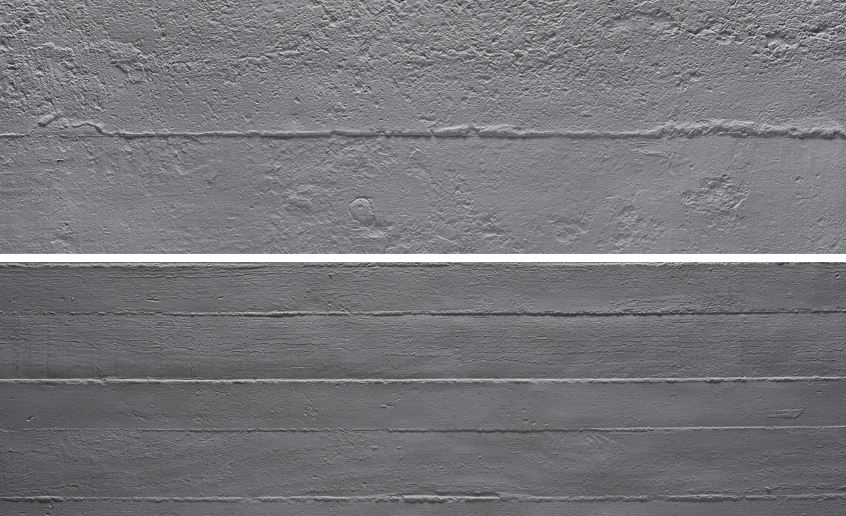
Catalogue texture references: Cast Concrete above, Wood Cement Panel below. Compare the line character; confirm colour and physical relief on the selected sample.
Review band direction across joints and around returns
Approve the sequence across a joint, rather than expecting every rammed earth panel to match automatically. Mark the face direction and panel IDs on the elevation. Distinguish deliberate variation from a continuation line that the design expects to cross a seam.
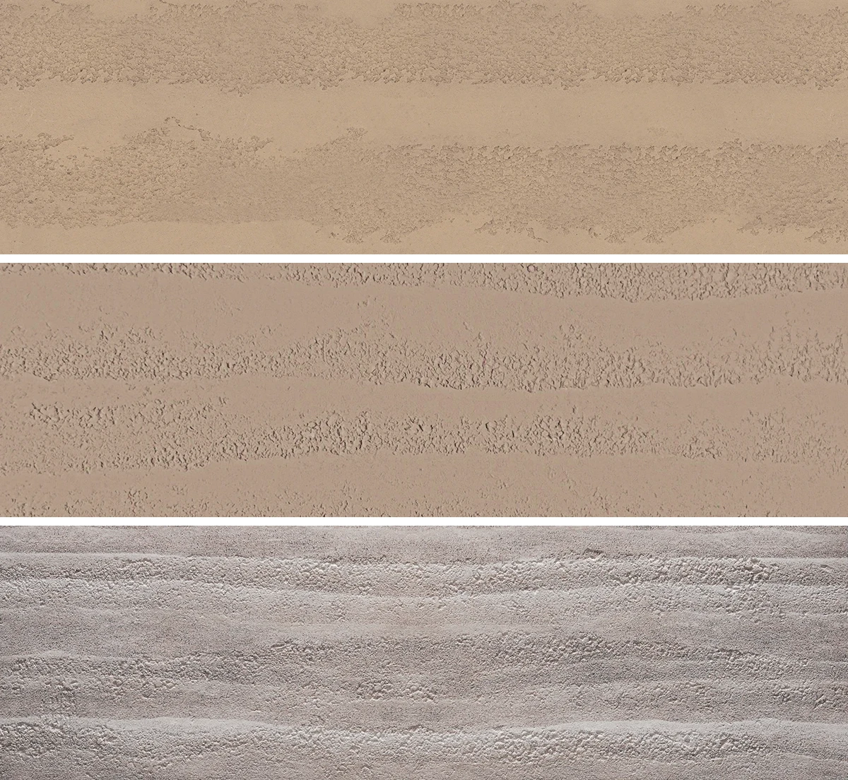
Top to bottom: Fine Rammed Earth, Rough Rammed Earth and 3D Printed Rough Rammed Earth. The photographs show different band character; they do not define a common physical scale or depth.
At a return, show whether the band should continue around the corner, stop at a trim or change direction. Review the corner and edge details with the installer before releasing the sheet sequence. Do not assume a catalogue sheet can bend to the required corner radius; obtain confirmation for the exact finish and format.
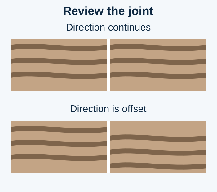
Appearance check at a joint. Schematic, not to scale: these drawn bands explain alignment only and do not promise bookmatching or continuous supplied patterns.
Record the accepted arrangement with the SKU, sample reference and drawing revision. If the installer proposes rotating a sheet or reusing an offcut, check its direction against the receiving location before counting it as usable material.
Check viewing distance and grazing light together
Use the final lighting direction when judging surface depth. Grazing light passes close to the surface and emphasizes relief through light and shadow; a more even wallwash serves a different appearance goal. ERCO's indoor Lightgap guidance describes this texture-emphasizing effect for wood, concrete and rough stone surfaces. Fixture geometry is specific to the lighting design, so the mock-up must use the project's intended arrangement.
Check the nearest occupied position first, where texture and joints are easy to examine, then step to the normal room approach to judge the overall band rhythm. Record these locations on the plan. There is no single viewing-distance cutoff that selects Fine over Rough Rammed Earth for every wall.
Selection rule: if a joint or band interruption remains unacceptable at the project's closest occupied viewing position under the intended light, hold appearance approval and change the sequence, joint detail, lighting or finish. The pass boundary is the agreed mock-up, not a catalogue photograph. Do not use a stronger grazing effect as a substitute for checking substrate flatness and the installed detail.
Screen the nominal formats against the wall elevation
Use the correctly oriented, usable sheet dimension to decide whether a full-height piece is possible. Published nominal sizes are a starting point; trimming, joints, perimeter details and pattern direction determine the finished layout.
| Product | Published nominal formats, mm | Layout check before ordering |
|---|---|---|
| Cast Concrete | 1220 × 2930 | Check usable width and height after the agreed trims. |
| Wood Cement Panel | 1200 × 3300 | Confirm that the intended line direction suits the full-height layout. |
| Fine Rammed Earth | 590 × 1200; 590 × 2400 | Check narrow-sheet repetition and horizontal joints. |
| Rough Rammed Earth | 600 × 1200; 1200 × 2400 | Check band transitions between the chosen formats. |
| 3D Printed Rough Rammed Earth | 600 × 1200; 1200 × 2400 | Confirm the colourway and sequence for the selected size. |
Geometric rule: if the required finished height H exceeds the confirmed usable sheet dimension in the approved texture direction, plan a horizontal joint or seek a confirmed alternative format. Do not rotate directional bands solely to make the sheet fit.
For an assumed 2700 mm finished piece, a 2400 mm nominal direction is already too short. A 2930 mm or 3300 mm nominal direction is only a candidate: verify the usable dimension and correct texture orientation before treating it as full height. This is geometry, not a manufacturing allowance.
A straight row with equal pieces can be checked as:
Wall width W = n × face width w + (n − 1) × joint width j + 2 × end allowance p.
Therefore w = [W − (n − 1)j − 2p] ÷ n.
Worked example, assumed inputs: W = 3628 mm, n = 3, j = 4 mm and p = 10 mm gives w = [3628 − 8 − 20] ÷ 3 = 1200 mm. Check: 3 × 1200 + 2 × 4 + 2 × 10 = 3628 mm. The joint and end allowances are arithmetic inputs, not recommended installation dimensions; a 1200 mm nominal sheet does not guarantee a 1200 mm usable face after trimming.
Use the sizes, thickness and weight guidance for dimension definitions and the custom-size cut schedule guide to assign cuts, direction and responsibility. “Lightweight concrete wall panels” describes a broad search category; obtain the selected MCM SKU's sheet weight and complete installed-assembly information separately for a wall-load review.
Compare the installed scope over the same ownership period
Compare the same wall elevation, appearance acceptance and owner-selected maintenance period. Sheet price alone misses the time spent sorting bands, finishing joints, checking the lighting and replacing a conspicuous piece later.
Same-period cost = supplied panels + preparation and installation + appearance mock-up and sequencing + access and protection + planned care and replacement within the chosen period.
| Cost input | Include in both options | What prevents an unfair comparison |
|---|---|---|
| Material and cutting | Required pieces, usable offcuts and separate spares | Compare a cut schedule, not wall area plus an invented waste percentage. |
| Layout labour | Sorting, direction marking, joint and return finishing | Identify who supplies the sequence and who accepts it. |
| Mock-up and access | Sample assembly, actual lighting review and later access | Agree the acceptance stage before the full wall is fixed. |
| Care and replacement | Cleaning approach, retained product reference and replacement work | Use the same period and access assumptions; ask for product-specific care guidance. |
Record quantities and labour hours against each scope item, then apply the actual quoted rates. Do not assume one texture has a fixed saving or service life. A rejected sequence can consume both replacement material and repeat labour; an accepted mock-up makes that scope visible before the order.
Confirm the assembly documents and send the sample brief
Keep visual approval and technical acceptance as separate records. Request the current product information and installation system for the selected substrate, adhesive, finish and application. Fire documentation must identify the tested product and assembly, report reference and method; a texture name cannot transfer a rating between products.
The current public scope of ASTM E84-26a describes surface-burning behaviour and reports flame-spread and smoke-developed indices. It also explains that specimen support can affect results and that the test does not cover every factor in a real-fire risk assessment. This method description establishes no HeyMaterials product rating. Have the project specifier review the exact applicable report and assembly before approval.
What to send us
| Item | Why we need it | Example format |
|---|---|---|
| SKU, colour and approval sample | Identify the exact finish to discuss | Product link and named sample |
| Elevation and proposed sequence | Review format and layout requirements | Dimensioned wall drawing, openings, face arrows and joint details |
| Viewing and lighting brief | Explain the intended appearance | Occupied positions, fixture reference and lighting direction |
| Substrate and application | Identify the proposed wall assembly | Dry interior location, wall build-up and photos |
| Quantity and destination | Define the quotation and delivery scope | Piece/area schedule, spares, city and country |
Request the shortlisted finish samples or send the wall brief for a quotation. Ask for confirmation of the selected format and the product documents needed by your project team before releasing the order.
Method and sources
Updated 19 October 2026. Product identities and nominal formats follow the supplied HeyMaterials catalogue records and the five linked product pages, checked on this date. Texture descriptions refer to the displayed catalogue images; physical sample review sets the project's appearance acceptance. The row calculation uses explicitly assumed inputs.
External primary references: ERCO Lightgap indoor grazing-light guidance for the light-and-shadow principle, and ASTM E84's current public scope for the limits of the surface-burning test description, both retrieved 19 October 2026. Neither supplies an MCM relief dimension, installation tolerance or HeyMaterials certification.
What to send us
Scroll the table horizontally to see all columns.
| Item | Why we need it | Example format |
|---|---|---|
| Finish or product reference | Identify the sample or product to quote | Product link or reference photo |
| Wall area and quantity | Define the quotation scope | Dimensioned drawing or quantity schedule |
| Application and substrate | Understand the proposed wall | Wall photos and substrate description |
| Destination | Discuss packing and shipping | City and country or port |
We reply within 24 hours.
Send your project details