Flexible Stone Installation
Flexible Stone Corners, Edges & Movement Joints
Updated
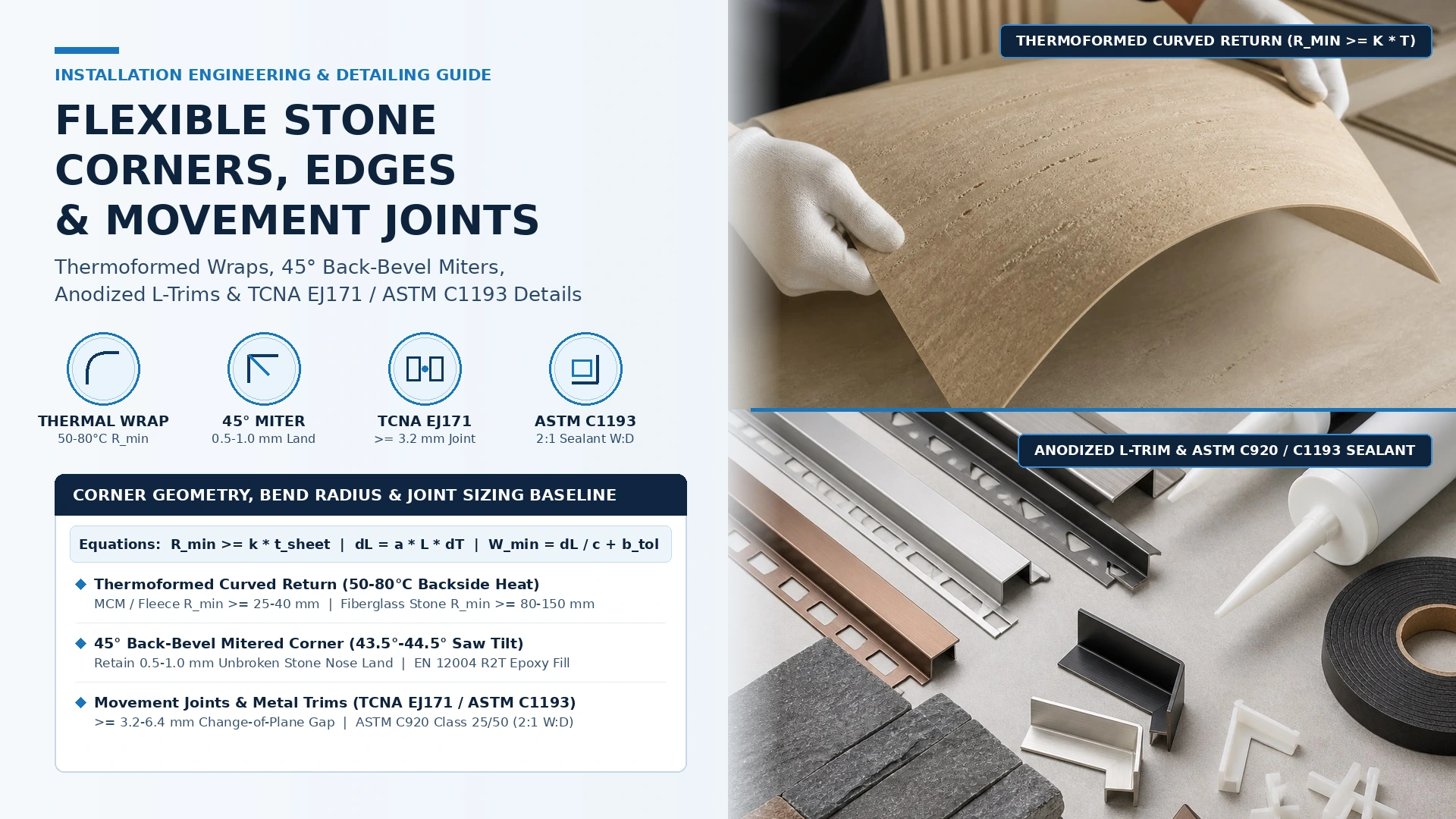
Forcing flexible stone panels around sharp 90-degree outside corners without backside heat-forming, beveling feather-thin miters freehand, or bridging substrate expansion joints causes stone cleavage cracking, elastic spring-back edge peel, exposed fiberglass seams, and water ingress rework. Engineer every transition before cutting production sheets: select between a thermoformed curved wrap (R_min >= k_bend * t_sheet heated at 50-80°C on the backing), a 43.5°-44.5° back-bevel miter retaining a 0.5-1.0 mm stone nose land, a dressed overlap butt joint, or an anodized aluminum L/J-trim with 1.5-2.0 mm expansion clearance, and honor all TCNA EJ171 / ASTM C1193 movement joints.
Quick Specs: Corner Wrapping, Miter, Edge Trim & Movement Joint Baseline
Scroll the table horizontally to see all columns.
| Corner / Joint Parameter | Engineering Acceptance Baseline | Reference Standard & Mock-Up Verification |
|---|---|---|
| Thermoformed Curved Corner Wrap (Heat & Bend) | Warm rear backing ONLY to 50-65°C (MCM/fleece) or 65-80°C (fiberglass-polyester) for 15-30 s; R_min >= 25-40 mm (MCM) or >= 80-150 mm (fiberglass slate/sandstone) | Never heat stone face or exceed 110-130°C resin scorch limit; clamp return legs 4-8 h in EN 12004 R2T / MS-polymer bed |
| 45° Back-Bevel Mitered Corner (Sharp 90° Return) | 43.5°-44.5° rail/bridge saw bevel leaving 0.5-1.0 mm unbroken stone nose land; 1.0-1.5 mm filled micro-joint | EN 13236 diamond blade (40-63 m/s); fill rear V-groove with stone-tinted EN 12004 R2T epoxy or MS-polymer |
| Square Overlap Butt Joint (Concealed Sightline Return) | Backside straight cut (<= +/- 0.5 mm / 1.2 m); 80-120 grit 45° micro-chamfer; color-matched mineral edge seal | Orient exposed panel thickness (t_panel + t_bed = 3.5-6.0 mm) away from primary traffic and daylight sightline |
| Anodized Aluminum / 304 & 316 Stainless Trim & Drip Edge | 3.0 / 4.5 / 6.0 mm L-trim, J-channel, or 15°-30° window-head drip edge with 1.5-2.0 mm expansion gap inside pocket | AA-M12C22A41 anodized aluminum (>= 15-25 um) or 316 marine stainless; isolate cut edge with ASTM C920 neutral silicone |
| Field & Perimeter Movement Joint Spacing (TCNA EJ171) | Every 6.0-7.6 m (20-25 ft) dry interior; every 2.4-3.6 m (8-12 ft) exterior / sunlit / wet walls; >= 3.2-6.4 mm at all inside corners & frames | TCNA Handbook Detail EJ171 & ANSI A108.02; never bridge structural expansion, control, or change-of-plane joints |
| Elastomeric Sealant Profile & Non-Staining Rating | 2:1 width-to-depth hourglass bead (d_sealant = 0.5 * W_joint) over closed-cell polyethylene backer rod (25-50% compression) | ASTM C1193 joint geometry + ASTM C920 Class 25/50 (+/- 25% to +/- 50% movement) + ASTM C1248 non-staining stone certification |
Standard installation engineering baseline. Verify substrate flatness, adhesive compatibility, and mock-up bond performance against the project submittal pack before full wall release.
Overview
External corners, window/door reveals, soffit drip edges, and change-of-plane movement joints determine whether a 1.5 to 3.0 mm flexible stone installation reads as monolithic architectural stonework or fails within months through edge delamination, chipped miter seams, and compressive tenting. While a flat wall field experiences uniform shear transfer into the adhesive bed, every corner and perimeter edge introduces biaxial peel stress, elastic bending spring-back, differential thermal expansion (Delta_L), and mechanical impact or moisture wicking along the exposed composite laminate.
To eliminate on-site cutting improvisation and non-billable tear-outs, lock four engineering controls on project shop drawings and full-scale mock-ups before starting Cutting & Drilling: (1) Corner Termination Architecture (Heat & Bend thermoformed wrap vs. 43.5°-44.5° back-bevel miter vs. dressed overlap butt joint vs. anodized aluminum / stainless L/J-trim), (2) Minimum Bend Radius & Backside Thermoforming Window (R_min >= k_bend * t_sheet at 50-80°C), (3) Movement Joint Continuity & Spacing (TCNA Handbook Detail EJ171 & ANSI A108.02 / A108.5), and (4) Elastomeric Joint Width-to-Depth Sizing (ASTM C1193 2:1 hourglass geometry with ASTM C920 / ASTM C1248 non-staining sealants). Compare the four primary corner and edge detailing systems in the engineering matrix below and request project-matched swatches via Request Samples:
| Corner / Edge Detailing System | Applicable Backing Class & Geometry Envelope | Shop / Field Fabrication & Bonding Protocol | Finished Visual Joint & Tolerance Baseline | Dominant Field Failure Mode & Engineering Prevention |
|---|---|---|---|---|
1. Thermoformed Curved Corner Wrap (Heat & Bend Monolithic Return) |
Breathable Fleece / MCM (1.5-2.5 mm): R_min >= 25-40 mm warm (50-65°C); Fiberglass-Polyester Slate / Sandstone / Travertine (1.5-3.0 mm): R_min >= 80-150 mm warm (65-80°C). Not for sharp R < 80 mm quartzite or 3D ribs |
Bullnose/chamfer substrate corner to >= R_min; heat rear backing only (50-80°C, 15-30 s); pre-form bend, let cool 60 s to lock shape, then bond with 100% EN 12004 R2T or high-tack MS-polymer and clamp 4-8 h |
0 mm corner seam (continuous stone grain wrapping around return; return leg width >= 100-150 mm before first flat-wall seam) |
Tensile stone cleavage cracking & elastic spring-back edge peel -> Never heat the stone face or exceed 110-130°C; never force cold fiberglass sheets around sharp 90° corners; use rigid strapping/tape clamps until adhesive cures |
2. 45° Back-Bevel Mitered Corner (43.5°-44.5° Architectural Miter) |
All flat fiberglass-polyester natural stone (1.5-3.0 mm), MCM sheets (1.5-2.5 mm), and 3D fluted/split-face panels (2.5-5.0 mm) on crisp 90° outside corners and column wraps |
Cut from backside on rail-guided plunge saw or wet bridge saw (EN 13236 diamond blade at 40-63 m/s) tilted to 43.5°-44.5°, leaving 0.5-1.0 mm unbroken stone nose land (t_land); dress bevel with 100-120 grit diamond pad |
1.0-1.5 mm micro-joint filled flush with stone-tinted EN 12004 R2T epoxy or ASTM C920 MS-polymer; lippage <= 0.5 mm |
Sawtooth "zipper" arris chipping & exposed black fiberglass line -> Never grind a 45° feather edge to 0.0 mm thickness freehand; retain 0.5-1.0 mm stone nose land, mask faces with low-tack tape, and cross-tape corner for 12-24 h |
3. Square Overlap Butt Joint (Lapped Return with Dressed Edge) |
Interior low-impact corners, utility alcoves, and budget-driven commercial fit-outs using 1.5-2.5 mm uniform-color MCM, rammed-earth, travertine, or slate sheets |
Terminate Panel A flush with corner plane; overlap Panel B across Panel A thickness (t_panel + t_bed = 3.5-6.0 mm) facing away from primary sightline; dress cut edge at 45° (0.3-0.5 mm) with 100-grit diamond block |
Exposed edge thickness 3.5-6.0 mm sealed with mineral-tinted stone touch-up coating (>= 95% color match) or sanded ASTM C920 bead |
Visible raw fiberglass lamination stripe & edge moisture wicking -> Orient overlap away from corridor entry/daylight sightline; pre-seal raw cut fiberglass edge before bonding; never use unsealed butt overlaps on exterior corners |
4. Anodized Aluminum / 304 & 316 Stainless Profile (L-Trim, J-Channel, Corner Bead & Drip Edge) |
High-traffic hospitality/retail corridors, elevator jambs, door/window casings, wainscot top caps, and exterior soffit drip edges (3.0 / 4.5 / 6.0 mm profile depth matched to t_panel + t_bed) |
Bed perforated anchoring leg into adhesive on substrate; leave 1.5-2.0 mm expansion clearance between dressed/sealed stone cut edge and inside wall of metal trim pocket |
Crisp 1.5-3.0 mm metallic reveal (AA-M12C22A41 anodized aluminum or brushed 304/316 stainless); >= 8-10 mm 15°-30° drip projection on soffits |
Edge buckling from 0 mm pinch fit & coastal chloride corrosion -> Never jam raw panel edges tight (0 mm) into metal channels; fill 1.5-2.0 mm pocket gap with ASTM C920 neutral silicone and specify 316 stainless or >= 25 um anodizing outdoors |
Details to review
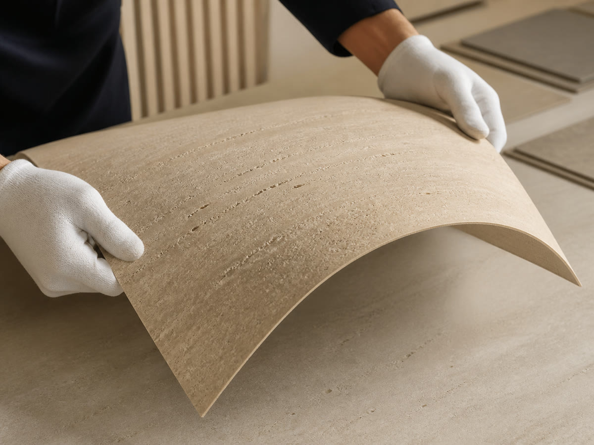
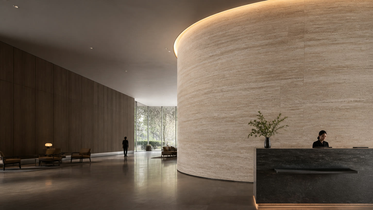
Use these visual references when reviewing the mock-up and work method with the project team.

Site checklist
1. Lock Corner Detail Before Cutting (`R_min` Wrap vs. `45°` Miter vs. `L-Trim`)
Select the exact corner geometry on shop drawings before releasing Cutting & Drilling-switching from a butt joint or L-trim to a 45° miter or thermoformed wrap changes finished panel width by 3 to 50+ mm and renders pre-cut sheets unusable.
Engineering Rule of Thumb: If an outside corner radius is tighter than R = 80 mm on fiberglass-polyester split stone (1.5-3.0 mm) or tighter than R = 300 mm on dense quartzite/3D fluted panels (2.5-5.0 mm) → prioritize a 43.5°-44.5° back-bevel miter or anodized metal L-trim because bending brittle metamorphic stone below R_min = k_bend * t_sheet exceeds the ultimate tensile strain (0.15-0.25%) of the mineral cleft layer and fractures the corner face.
2. Apply `50-80°C` Thermoforming Heat Strictly to the Rear Backing
Check panel carrier composition in Composition & Backing and Dimensions, Weight & Flexibility before heat-forming outside corners or column wraps.
Engineering Rule of Thumb: If thermoforming a curved corner return (25 mm <= R <= 150 mm) → heat only the rear polymer/fiberglass backing to 50-65°C (MCM / textile fleece) or 65-80°C (polyester-fiberglass stone) for 15-30 seconds using a variable-temperature heat gun held 100-150 mm away, and never exceed 110-130°C because overheating scorches unsaturated polyester resin and delaminates the stone veneer.
3. Retain a `0.5-1.0 mm` Stone Nose Land on `45°` Back-Bevel Miters
Cut mitered corners on a rail-guided plunge saw or wet bridge saw (EN 13236 continuous-rim diamond blade at 40-63 m/s) clamped flat on a sacrificial MDF/XPS spoilboard.
Engineering Rule of Thumb: If detailing a sharp 90° mitered outside corner → tilt the diamond saw to 43.5°-44.5° and stop the bevel 0.5 to 1.0 mm short of the front stone face (t_land = 0.5-1.0 mm) rather than grinding a 0.0 mm feather edge because a zero-thickness mineral edge spalls into a jagged "zipper" line under blade vibration and corridor impact.
4. Honor `TCNA EJ171` Movement Joints & `ASTM C1193` `2:1` Sealant Geometry
Map all structural expansion joints, substrate transitions, internal 90° corners, and door/window perimeters during the Existing Surfaces survey and carry them cleanly through the stone finish per Joints & Sealing.
Engineering Rule of Thumb: If two walls meet at an internal 90° corner, abut a door/window frame, or cross a structural substrate joint (TCNA EJ171) → leave an unbridged 3.2 to 6.4 mm (1/8-1/4 in) interior gap (9.5-12.7 mm exterior field joint every 2.4-3.6 m) filled with ASTM C920 Class 25/50 neutral sealant at a 2:1 width-to-depth ratio over closed-cell backer rod (ASTM C1193) because rigid grouting or continuous sheet bridging causes compressive tenting and cohesive corner cracking.
Key steps
Step 1: Map All Corners, Terminations & `TCNA EJ171` Movement Joints on Elevations
Before ordering or cutting sheets, mark every external corner (
90°miter, curved wrapR_min, or metal trim), internal corner (3.2-6.4 mmmovement joint), window/door casing reveal, ceiling/floor isolation gap, and structural expansion joint on dimensioned PDF elevations. Verify existing wall plumbness and flatness (<= 3 mm in 3.0 munderANSI A108.02, reduced to<= 1.5 mmwithin150 mmof mitered corners) during your Existing Surfaces survey.Step 2: Select the Corner Detail & Calculate Final Sheet Takeoff Widths
Choose between a thermoformed wrap,
43.5°-44.5°back-bevel miter (x_mitersetback), overlap butt joint, orL/J-trimprofile for each transition and adjust panel cut dimensions in Cutting & Drilling before production sawing. Share your SKU reference, corner photos, and dimensioned elevations via Get a Quote or the floating WhatsApp contact for a project-specific engineering review. We reply within 24 hours.Step 3: Execute & Approve a Full-Scale Corner & Joint Mock-Up
Build a full-scale site mock-up incorporating the actual project SKU, adhesive bed (
EN 12004 R2T,C2TES1/S2, or MS-polymer per Adhesives & Substrates), corner return (>= 100-150 mmleg),ASTM C920/ASTM C1248sealant bead, and grazing architectural lighting. Record the approved bend radius (R_min), grain direction arrow, miter land thickness (0.5-1.0 mm), and cured sealant color in the signed quality log.Step 4: Install Corners First & Honor Continuous `ASTM C1193` Movement Joints
Start wall installation at external corners and columns, working outward toward internal corners and field movement joints so cut tolerances accumulate at concealed or caulked perimeters rather than visible outside arrises. Maintain
>= 95%adhesive contact within100 mmof all corners (ANSI A108.5), insert closed-cell polyethylene backer rod into all movement joints, and toolASTM C920neutral sealant to a2:1width-to-depth hourglass profile per Joints & Sealing.
Thermoformed Curved Returns (`50-80°C`) vs. `45°` Back-Bevel Miters: Backing Mechanics & Minimum Bend Radius Matrix
Whether a flexible stone panel can wrap around an outside corner or cylindrical column (see Curved Walls & Columns) without cracking depends on the tensile strain limit of the stone wearing layer (epsilon_max ~ 0.15-0.25%), the glass-transition temperature (T_g) of the polymer carrier, and the sheet thickness (t_sheet). When a composite laminate of thickness t_sheet bends around a radius R, outer-fiber tensile strain on an external (convex) bend equals epsilon_bend = t_sheet / (2 * R). Heating the rear backing softens the polymer matrix and shifts the neutral axis toward the brittle mineral face, reducing tensile stress on the stone layer by 40-60%. Calibrate your shop and site bending parameters against this backing-specific matrix:
| Panel Backing Architecture & Stone Veneer Class | Nominal Thickness (t_sheet) |
Cold Minimum Bend Radius (20°C Ambient, Longitudinal Axis) |
Warm Thermoformed Min Radius (50-80°C Backside Heat) |
Backside Heating Window & Clamping Protocol | Dominant Corner Wrapping Failure Mode & Engineering Prevention |
|---|---|---|---|---|---|
Breathable Textile Fleece / Modified Mineral Composite (MCM Rammed-Earth, Travertine, Concrete & Linear Sheets) |
1.5 - 2.5 mm |
R_min >= 150 - 200 mm (k_bend = 80-100) |
R_min >= 25 - 40 mm (k_bend = 15-20 rounded bullnose return) |
Heat rear fleece backing to 50-65°C for 15-20 s with variable heat gun (100-150 mm standoff); roll firmly with hard rubber seam roller |
Surface micro-crazing on tight cold bends (R < 100 mm) -> Warm rear backing to 55-65°C before wrapping bullnose corners; stagger vertical seams >= 150 mm away from corner tangent |
Unsaturated Polyester Resin + Woven E-Glass (Split Slate, Schist & Fine Sandstone) |
1.5 - 2.5 mm |
R_min >= 300 - 450 mm (k_bend = 150-180 along 1200/2400 mm length) |
R_min >= 80 - 120 mm (k_bend = 45-55 with 65-80°C backside heat) |
Heat fiberglass backing evenly to 65-80°C (20-30 s); bend smoothly over pre-shaped substrate radius, let cool 60 s, then bed in EN 12004 R2T / MS-polymer |
Delamination & elastic spring-back edge lifting (24-72 h post-install) -> Never wrap sharp 90° corners (R < 80 mm); use mechanical strapping/painter’s tape clamps for 4-8 h until adhesive cures |
| Fiberglass-Polyester Natural Travertine, Limestone & Marble Veneers | 2.0 - 3.0 mm |
R_min >= 450 - 600 mm (k_bend = 180-220 longitudinal; verify transverse direction) |
R_min >= 120 - 200 mm (k_bend = 60-80 with 70-80°C backside heat) |
Pre-seal porous face; warm fiberglass backing to 70-80°C; support entire arc with 100% back-buttered adhesive transfer (ANSI A108.5) |
Open travertine pore-bridging cracks along corner apex -> Test longitudinal vs. transverse bend direction on full-size sample; switch to 43.5°-44.5° back-bevel miter for sharp geometric corners |
| Dense Metamorphic Quartzite & Thick 3D Fluted / Split-Face Panels | 2.5 - 5.0 mm |
R_min >= 600 - 1,000 mm (gentle architectural curves only; zero tight bends) |
R_min >= 350 - 500 mm (fluted panels bend only parallel to flutes; never across ribs) |
Do not attempt tight corner thermoforming; fabricate 90° corners using 43.5°-44.5° wet bridge-saw miter or anodized aluminum L-trim |
Brittle quartz fracture & resin scorching (> 110-130°C) -> Never overheat thick quartzite/3D sheets trying to force a tight bend; always specify mitered returns or interlocking factory corner units |
Engineering Rule of Thumb: Never apply a heat gun directly to the front natural stone face or exceed 80°C panel temperature (110-130°C resin scorch ceiling)-heating the stone face creates a steep thermal gradient across the 0.5-1.5 mm mineral cleft that blisters the polyester resin bond and discolors iron-bearing slate and travertine.
Engineering Formulas: Minimum Bend Radius (`R_min`), `45°` Miter Setback & `TCNA EJ171 / ASTM C1193` Thermal Joint Sizing
Use these four closed-form engineering equations to verify whether a curved corner can be wrapped without tensile fracture, set precision 45° bevel saw stops, and size movement accommodation joints and backer rods across interior and exterior elevations:
1. Minimum Corner Bend Radius & Outer-Fiber Strain: R_min = k_bend * t_sheet ; epsilon_bend = t_sheet / (2 * R) <= epsilon_allow
2. 90° Curved Corner Arc Takeoff Length: L_arc = (pi / 2) * (R_sub + 0.5 * t_sheet) + L_leg1 + L_leg2
3. 45° Back-Bevel Corner Miter Setback: x_miter = (t_panel - t_land) * tan(theta_bevel)
4. Thermal Expansion & ASTM C1193 / C920 Joint Width: Delta_L = alpha_eff * L_bay * Delta_T ; W_min = (Delta_L / c_move) + b_tol ; d_sealant = 0.5 * W_joint
Where:
R_min= minimum safe centerline bend radius (mm);t_sheet= nominal panel thickness (1.5-5.0 mm);k_bend= dimensionless backing bend factor (15-20warmMCM/fleece;45-60warm fiberglass-slate;150-220cold fiberglass stone)epsilon_bend= flexural tensile strain in outer stone face (<= 0.0015 to 0.0025(0.15-0.25%) uncracked mineral limit);R_sub= substrate corner radius (mm);L_leg1, L_leg2= continuous straight return legs on either side of corner (>= 100-150 mm)x_miter= horizontal back-bevel depth (mm);t_land= unbroken stone nose land (0.5-1.0 mm);theta_bevel= saw bevel angle (43.5°-44.5°for a90°outside corner with internal epoxy key space)Delta_L= unrestrained linear thermal movement (mm);alpha_eff= effective thermal expansion coefficient (0.014 mm/(m·°C)for fiberglass-polyester stone veneer;0.011 mm/(m·°C)forMCM/cementitious assemblies;0.023 mm/(m·°C)for aluminum trims)L_bay= distance between movement joints (m,<= 2.4-3.6 mexterior / sunlit interior;<= 6.0-7.6 mdry interior perTCNA EJ171);Delta_T= design surface temperature swing (°C,50-70°Cdark exterior facade;15-25°Cinterior)c_move=ASTM C920cyclic movement class fraction (0.25forClass 25+/- 25%sealant;0.50forClass 50+/- 50%);b_tol= cutting & alignment tolerance (2.0 mminterior;6.0-8.0 mmexterior baseline perTCNA EJ171);d_sealant= centerline sealant depth (2:1width-to-depth ratio underASTM C1193)
Worked Example 1: Thermoformed 90° Bullnose Column Return & Arc Sheet Width (t_sheet = 2.2 mm)
An interior lobby column has 90° bullnose corners shaped to R_sub = 100 mm, clad with t_sheet = 2.2 mm fiberglass-backed split sandstone (k_bend = 45 when backside-heated to 70°C), with L_leg1 = L_leg2 = 200 mm return legs:
- Minimum Safe Thermoformed Radius Check:
R_min = 45 * 2.2 mm = 99.0 mm <= R_sub (100 mm)-> Pass (outer-fiber strainepsilon_bend = 2.2 / (2 * 100) = 1.1%absorbed by softened70°Cpolyester-fiberglass carrier without stone cracking). - Required Continuous Panel Wrap Width (
L_arc):L_arc = 1.5708 * (100 + 1.1) + 200 + 200 = 158.8 + 400 = 558.8 mm(fits cleanly within a single600 mmsheet width with41.2 mmtrim margin).
Worked Example 2: Exterior Facade TCNA EJ171 Movement Joint & ASTM C1193 Sealant Sizing
A south-facing exterior charcoal slate facade (alpha_eff = 0.014 mm/(m·°C)) places vertical movement joints at L_bay = 3.6 m (11.8 ft) centers across a seasonal/solar surface temperature swing of Delta_T = 65°C (-10°C winter night to +55°C summer sun), sealed with ASTM C920 Class 25 (c_move = 0.25) neutral silicone:
- Unrestrained Thermal Expansion (
Delta_L):Delta_L = 0.014 * 3.6 * 65 = 3.28 mmper bay. - Required Sealant Joint Width (
W_min&TCNA EJ171Check):W_min = (3.28 / 0.25) + 0.0 = 13.12 mmminimum elastomeric width -> specifyW_joint = 13.0 mm (1/2 in)(>= 12.7 mmTCNA EJ171minimum for3.6 m / 12 ftexterior spacing), installed over a16 mm (5/8 in)closed-cell polyethylene backer rod (~25%compression) set to a centerline sealant depth ofd_sealant = 0.5 * 13.0 = 6.5 mm (1/4 in)(ASTM C11932:1hourglass profile).
Movement Joint Locations (`TCNA EJ171`), Window/Door Reveals & Drip-Edge Termination Matrix
Flexible stone panels are thin (1.5-3.0 mm), but their woven E-glass fiberglass or mineral-fleece backing exhibits high in-plane tensile stiffness (8-15 GPa). Bridging an active substrate control joint or jamming cut edges tight (0 mm clearance) against rigid door frames, ceiling soffits, or internal wall corners transfers full structural shrinkage and thermal shear directly into the 2.2-3.5 mm adhesive bed. Detail every perimeter and change-of-plane interface using this TCNA EJ171, ANSI A108.5, and ASTM C1193 matrix and cross-reference Water & Weather Resistance:
| Transition / Interface Location | Mandatory Joint Width & Spacing (TCNA EJ171 / ASTM C1193) |
Backer Rod, Bond-Breaker & Sealant Specification | Edge Trim / Flashing & Adhesive Coverage (ANSI A108.5) |
Dominant Field Failure Mode & Engineering Prevention |
|---|---|---|---|---|
Internal 90° Wall-to-Wall Corners (Change of Plane) |
3.2 - 6.4 mm (1/8 - 1/4 in) continuous vertical isolation gap (never 0 mm tight butt or rigid grout) |
Polyethylene bond-breaker tape at corner apex or 6-8 mm closed-cell backer rod + ASTM C920 Class 25 (+/- 25%) neutral silicone/MS-polymer (ASTM C1248 non-staining) |
>= 80% interior / >= 95% wet-area adhesive contact right up to both corner edges; rake adhesive clean out of the 3.2-6.4 mm joint channel |
Compressive corner crushing & diagonal shear cracking -> Never bridge internal 90° corners with continuous sheets or hard cementitious grout; rake adhesive out of the corner gap before curing |
| Floor Base, Ceiling Soffit & Millwork Perimeters | 6.4 mm (1/4 in) preferred (>= 3.2 mm / 1/8 in absolute minimum) perimeter isolation joint or shadow reveal |
Concealed behind baseboard/cove trim indoors, or filled with ASTM C920 elastomeric sealant over bond-breaker tape in wet/commercial zones |
Anodized aluminum Z-shadow reveal bead (6-10 mm recess) or J-channel base stop; keep bottom stone edge >= 6 mm above wet floor slabs |
Capillary moisture wicking from wet floor mopping & slab deflection buckling -> Never rest raw cut bottom panel edges directly on structural floor slabs (0 mm gap); pre-seal bottom cut edges |
| Window Jambs, Door Casings & Elevator Frames | 3.2 - 5.0 mm (1/8 - 3/16 in) flexible perimeter caulk joint around all rigid metal, wood, or stone frames |
Bond-breaker tape against frame return + ASTM C920 neutral-cure silicone or MS-polymer color-matched to stone or frame finish |
Match 4.0-6.5 mm total cladding build-up (t_panel + t_bed) to casing depth or cap with anodized aluminum L-trim (1.5-2.0 mm internal pocket gap) |
Door frame racking cracks & water intrusion around exterior windows -> Never butt raw cut stone tight against vibrating door/elevator jambs; isolate with a >= 3.2 mm flexible sealant bead |
| Exterior Window Heads, Parapets & Soffit Drip Edges | 15°-30° sloped drip edge projecting >= 8-10 mm past vertical face + 3.2-5.0 mm sealed skyward termination |
100% EN 12004 R2T / MS-polymer bed (>= 95% coverage per ANSI A108.5) + continuous top-edge flashing and ASTM C920 Class 50 weather seal |
Architectural anodized aluminum (>= 25 um) or 316 stainless steel drip-edge profile at all horizontal window heads and soffit transitions |
Rainwater capillary wrap-around (back-wetting) & freeze-thaw peel -> Never terminate overhead soffit panels with an unprotected flat horizontal joint; install a projecting metal drip lip |
| Structural Expansion, Control & Substrate-Change Joints | Match structural joint width (>= 9.5-12.7 mm / 3/8-1/2 in) at <= 2.4-3.6 m (8-12 ft) exterior / <= 6.0-7.6 m (20-25 ft) dry interior spacing |
Compressible closed-cell polyethylene backer rod (diameter = 1.25-1.33 * W_joint) + ASTM C920 Class 50 sealant at 2:1 width-to-depth ratio (ASTM C1193) |
Two-piece architectural expansion joint cover profile or opposing L-trim edge stops aligned strictly with substrate joint edges |
Three-sided sealant tearing & multi-panel "tenting" delamination -> Never bridge a substrate joint or allow sealant to bond to the backer-less base of a joint groove (3-sided adhesion) |
Engineering Rule of Thumb: Whenever a drywall partition transitions to a concrete shear wall, CMU masonry shaft, or wood furring along the same flat elevation (TCNA EJ171), treat the substrate interface line as a mandatory 3.2-6.4 mm movement joint-cutting the flexible stone panel cleanly over the substrate junction prevents differential drying shrinkage from ripping the fiberglass backing in half.
5-Year Corner Delamination, Water Ingress & Labor TCO Ledger
Improvised corner and joint detailing accounts for less than 5% of wall material cost but drives over 70% of post-handover architectural rejections, water-ingress callbacks, and multi-panel replacement claims. Compare the upfront engineering prevention baseline against the 5-year Total Cost of Ownership (TCO) rework multiplier across these five field failure modes, and cross-reference Troubleshooting and Over-Tile Cost Scope:
| Corner / Joint Field Failure Scenario | Root Mechanical / Chemical Cause | Upfront Engineering Prevention Baseline | 5-Year TCO Rework Multiplier (Demolition + Replacement + Downtime) |
|---|---|---|---|
Cold-Wrapped 90° Corner Cracking & Elastic Spring-Back Peel |
Bending fiberglass-polyester stone cold around < 80 mm radius or using standard acrylic dispersion glue without clamping |
Backside thermoforming (65-80°C, R >= R_min) + EN 12004 R2T / high-tack MS-polymer + 4-8 h corner strapping |
8x-14x corner labor cost: corner splits within 48 h to 4 weeks, requiring demolition of both intersecting sheets and quarry-lot color matching |
| Chipped "Zipper" Miter Line & Exposed Black Fiberglass Core | Grinding 45° miters freehand to a 0.0 mm feather edge or cutting from front stone face with high-RPM grinder |
Rail/bridge saw 43.5°-44.5° backside bevel retaining 0.5-1.0 mm stone nose land + 100-grit diamond dressing + tinted R2T epoxy |
6x-10x miter fabrication cost: rejected by architect at snagging walk-through; forces full corner column strip-out and re-cladding |
Compressive Panel Tenting Across Bridged TCNA EJ171 Joints |
Bonding continuous sheets across structural control joints, substrate changes, or > 3.6 m exterior bays without expansion gaps |
Full-depth 3.2-12.7 mm movement joints aligned with substrate joints + ASTM C1193 2:1 sealant over closed-cell backer rod |
12x-20x joint detail cost: thermal expansion buckles panels off the wall in a 0.5-2.0 m shear wave; creates overhead falling-cladding hazard |
Exterior Corner & Window-Head Water Ingress (Back-Wetting) |
Omitting 15°-30° soffit drip edges, leaving < 95% adhesive voids at edges, or using rigid acrylic caulk outdoors |
>= 95% ANSI A108.5 edge adhesive transfer + anodized aluminum / 316 stainless drip edge + ASTM C920 Class 50 weather seal |
15x-25x trim & sealant cost: trapped water behind veneer triggers freeze-thaw spalling, substrate rot, and interior moisture damage |
| Hydrophobic "Picture-Frame" Staining Along Joint Edges | Using uncertified fluid-bleeding silicone or smearing polyurethane adhesive onto unsealed porous travertine/marble | Pre-sealing porous stone faces + specifying ASTM C1248 certified non-staining neutral sealant + low-tack masking tape during tooling |
10x-16x sealant material cost: migrated silicone oils cannot be poulticed out of thin 2 mm stone clefts, forcing permanent panel replacement |
Details to Prepare for Corner, Edge & Movement Joint Engineering Review
Before releasing production cutting or ordering custom pre-mitered / pre-formed corner kits (see Custom-Size Flexible Stone Cut Plan), send the five engineering records listed in the What to send us table below via Get a Quote, Request Samples, or the floating WhatsApp contact:
- Panel SKU, Sheet Thickness (
mm) & Backing Class: Identify the exact product code (1200 x 600 mmor2400 x 1200 mm), thickness (1.5-5.0 mm), and carrier (fiberglass-polyester,breathable fleece, orMCM). - Dimensioned Plan / Elevation Drawings & Corner Schedule: Provide a dimensioned PDF marking every external
90°corner, curved return (R_sub mm), internal corner, and door/window reveal. - Selected Corner & Edge Termination Method: State whether each transition uses a thermoformed wrap (
50-80°C),43.5°-44.5°back-bevel miter (0.5-1.0 mmland), overlap butt joint, or3.0 / 4.5 / 6.0 mmmetalL/J-trim. TCNA EJ171Movement Joint Spacing, Exposure &ASTM C920Sealant TDS: Specify interior vs. exterior climate (Delta_T °C), bay spacing (m), substrate transitions, and candidateASTM C920 / C1248sealant datasheets.- Full-Scale Mock-Up Photos, Net Area (
m²) & Delivery Destination: Attach labelled mock-up photos showing grain direction and edge finish, plus net/gross area (m²) and destination city/port. We review your submittal package and reply within 24 hours.
Frequently asked questions
Can flexible stone panels wrap directly around a sharp 90-degree outside corner without cutting?
No-never force a flexible stone panel cold around a sharp 90° corner (R < 25-80 mm). Even though the sheet bends over curved walls, bending a 2.0 mm laminate around a sharp 2 mm corner radius generates 50% outer-fiber tensile strain (epsilon = t / 2R), which immediately fractures natural slate, sandstone, travertine, or quartzite and causes elastic spring-back peeling. For a seamless wrapped look, round the substrate corner to at least R_min = 25-40 mm (MCM/fleece heated to 50-65°C on the backside) or R_min = 80-150 mm (fiberglass-polyester stone heated to 65-80°C on the backside). If the architectural design requires a crisp, sharp 90° corner, use a 43.5°-44.5° back-bevel miter (0.5-1.0 mm stone nose land) or an anodized aluminum / stainless steel L-trim.
What temperature should a heat gun be set to when thermoforming flexible stone corners, and which side do you heat?
Always apply hot air strictly to the rear polymer, fiberglass, or textile-fleece backing-never directly to the front natural stone face. Set a variable-temperature industrial heat gun so the panel backing surface reaches 50-65°C (122-149°F) for MCM / breathable fleece sheets or 65-80°C (149-176°F) for fiberglass-polyester natural stone sheets, sweeping continuously 100-150 mm from the surface for 15-30 seconds. Never exceed 110-130°C (230-266°F), which scorches unsaturated polyester resin, releases styrene fumes, and permanently delaminates the stone cleft layer.
How do you cut a clean 45-degree mitered corner on flexible stone without chipping the stone edge?
Clamp the panel flat stone face down on a clean 18 mm MDF or extruded polystyrene (XPS) sacrificial spoilboard and cut from the backside using a track-guided plunge saw or sliding wet bridge saw fitted with an EN 13236 continuous-rim diamond blade (40-63 m/s peripheral speed; see Cutting & Drilling). Tilt the blade to 43.5°-44.5° and set the depth stop to leave a 0.5 to 1.0 mm unbroken stone nose land (t_land) rather than feathering the mineral face to 0.0 mm. Dress the bevel lightly with a 100-120 grit diamond hand pad, mask both faces with low-tack painter’s tape, fill the rear V-pocket with stone-tinted EN 12004 R2T epoxy or MS-polymer, and cross-tape the corner for 12-24 hours.
Can flexible stone sheets bridge across existing substrate expansion joints or internal 90-degree wall corners?
No. Under TCNA Handbook Detail EJ171 and ANSI A108.02, all structural expansion, control, isolation, seismic, and substrate-change joints-as well as all internal 90° wall-to-wall, wall-to-floor, and wall-to-ceiling changes of plane-must continue unobstructed through the flexible stone cladding. Because the woven fiberglass backing has high in-plane tensile stiffness (8-15 GPa), bridging an active joint causes the sheet to buckle ("tent") under compression or rip diagonally under tension. Leave a 3.2-6.4 mm (1/8-1/4 in) interior change-of-plane gap (9.5-12.7 mm on exterior bays spaced every 2.4-3.6 m) and fill with ASTM C920 elastomeric sealant over closed-cell backer rod per Joints & Sealing.
Why must elastomeric corner and movement joint sealants follow a 2:1 width-to-depth ratio over backer rod?
Under ASTM C1193 (Standard Guide for Use of Joint Sealants), an elastomeric sealant bead (ASTM C920 Class 25 or Class 50) performs like an accordion in tension and compression only when bonded strictly to the two opposing stone edges (two-sided adhesion) with a centerline depth equal to half the joint width (d_sealant = 0.5 * W_joint). If sealant is gunned full-depth into a joint without a closed-cell polyethylene backer rod or bond-breaker tape, three-sided adhesion locks the bottom of the bead to the rigid substrate, multiplying peel stress by 3x-4x and tearing the sealant or stone edge during the first thermal cycle.
When should anodized aluminum or stainless steel L-trims and J-channels be specified instead of mitered corners?
Specify architectural metal trims (3.0 mm, 4.5 mm, or 6.0 mm profile depth matched to panel thickness plus the 2.2-3.5 mm collapsed adhesive bed) in four high-risk zones: (1) high-traffic commercial corridors, hotel luggage paths, and retail columns where luggage carts or pedestrian impact can chip mitered stone arrises, (2) elevator jambs, door casings, and wainscot top caps where one panel edge remains exposed, (3) exterior window heads and soffit transitions requiring a 15°-30° projecting drip lip (>= 8-10 mm) to shed rainwater, and (4) rapid multi-room hospitality rollouts where metal trims eliminate on-site bevel sawing. Always leave a 1.5-2.0 mm expansion gap inside the trim pocket sealed with ASTM C920 neutral silicone.
Continue planning
Use these related guides before fixing details or releasing material.
Calibrate backside sawing & 45° miter bevel cuts
Set EN 13236 diamond blade speeds (40-63 m/s), sacrificial spoilboards, and 0.5-1.0 mm miter nose lands before cutting corner sheets.
Read moreSpecify ASTM C920 sealants & ASTM C1248 stain testing
Coordinate movement joint fillers, closed-cell backer rods, and breathable impregnating sealers across all corner and edge details.
Read moreSelect EN 12004 R2T & MS-polymer corner adhesives
Match high-grab MS-polymer and 2-part polyurethane adhesives to resist elastic spring-back peel stress on wrapped corners.
Read moreEngineer curved wall & cylindrical column wraps
Coordinate minimum bend radii (R_min), longitudinal vs. transverse panel grain direction, and staggered seam layouts on columns.
Read moreDetail commercial lobby & corridor feature walls
Integrate high-traffic outside corner protection, millwork shadow reveals, and NEC 314.20 electrical box setbacks on interior walls.
Read moreSubmit corner elevations & mock-up specs for review
Send your SKU code, corner radii, trim profiles, and dimensioned PDF elevations for engineering review within 24 hours.
Read moreWhat to send us
Scroll the table horizontally to see all columns.
| Item | Why we need it | Example format |
|---|---|---|
| Panel SKU, sheet thickness (mm) and backing class | Match minimum bend radius (R_min) or 45-degree miter bevel to composite carrier | Product code, sheet size (1200x600 or 2400x1200 mm), thickness and backing type |
| Dimensioned plan / elevation drawings and corner schedule | Locate all 90-degree outside corners, curved returns (R_sub mm), inside corners and reveals | Dimensioned PDF marking external corners, column radii and door/window frames |
| Selected corner and edge termination detail | Confirm thermoformed wrap (50-80°C), 43.5°-44.5° miter (0.5-1.0 mm land) or metal L/J-trim | Detail selection per corner with trim depth (3.0 / 4.5 / 6.0 mm) or miter sketch |
| TCNA EJ171 movement joint spacing, exposure and ASTM C920 sealant TDS | Verify thermal expansion width (W_min), 2:1 backer-rod depth (ASTM C1193) and ASTM C1248 non-staining | Interior vs exterior ΔT notes, bay spacing (m) and proposed sealant data sheets |
| Full-scale mock-up photos, net wall area (m2) and delivery destination | Tie approved corner return and grain direction to production batch and freight scope | Labelled mock-up photos, net/gross area schedule (m2) and destination city/port |
We reply within 24 hours.
Send your project details