Flexible Stone Installation
Cutting & Drilling Flexible Stone Panels
Updated
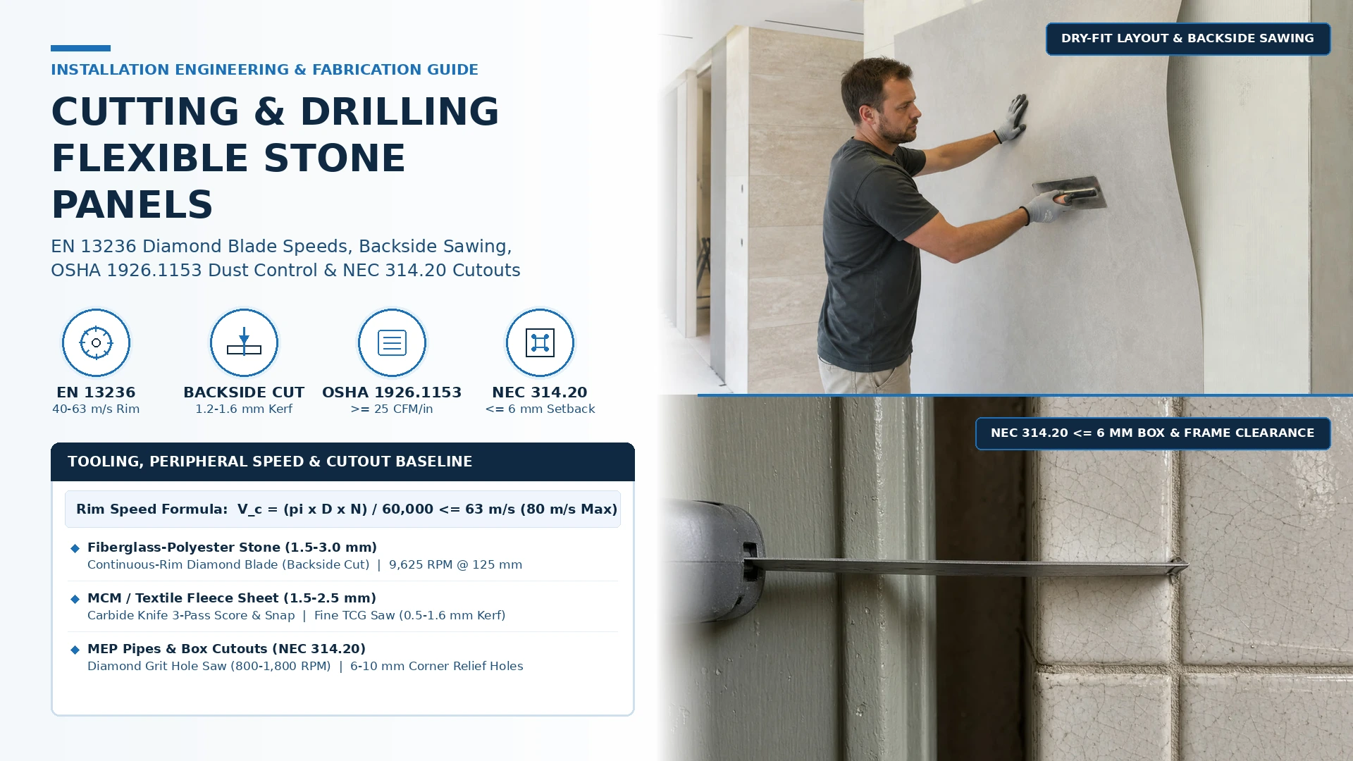
Cutting or drilling flexible stone panels with wood-tooth blades, dull utility knives, or uncalibrated high-RPM grinders causes stone cleft spalling, polyester-fiberglass backing delamination, thermal resin scorching, corner stress cracks, and costly panel waste and rework. Treat panel fabrication as a controlled machining process: match the cutting method to the panel backing architecture (fiberglass-polyester resin vs. breathable fleece/MCM), maintain continuous-rim diamond blade peripheral speed within 40 to 63 m/s (EN 13236 / ANSI B7.1), enforce wet suppression or >= 25 CFM per blade-inch HEPA extraction (OSHA 29 CFR 1926.1153), and pre-drill 6-10 mm corner relief radii on all rectangular cutouts before production release.
Quick Specs: Cutting, Drilling & Edge Machining Baseline
Scroll the table horizontally to see all columns.
| Machining Parameter | Engineering Acceptance Baseline | Reference Standard & Shop / Field Check |
|---|---|---|
| Fiberglass-Polyester Natural Stone (1.5-3.0 mm) | Continuous-rim diamond blade (1.2-1.6 mm kerf) or 40-60T TCG carbide blade from backside | EN 13236 / ANSI B7.1 track saw, wet bridge saw, or variable-speed grinder on spoilboard |
| MCM / Breathable Fleece Backing (1.5-2.5 mm) | 3-pass heavy-duty utility score-and-snap (0.5-0.8 mm kerf) or continuous-rim diamond blade | Clamped aluminum straightedge guide; 80-120 grit diamond hand-pad edge dressing |
| Diamond Blade Peripheral Speed Window | Optimal 40-63 m/s (<= 9,625 RPM on 125 mm blade); absolute safety ceiling 80 m/s | EN 13236 / ANSI B7.1 spindle RPM check; prevents > 110-130°C polyester resin scorch |
| Silica & Fiberglass Dust Control | Wet feed >= 0.5 L/min OR shrouded vacuum >= 25 CFM/in blade diameter + 99.97% HEPA H13/H14 | OSHA 29 CFR 1926.1153 Table 1 compliance (8-h TWA PEL <= 50 ug/m3) |
| MEP Core Drilling & Corner Relief | Diamond hole saw (800-1,800 RPM) face-down; 6-10 mm corner relief holes on box cutouts | Clamped >= 12 mm plywood backing board; >= 25-30 mm uncut bridge to sheet edge |
| Electrical Box Setback & Perimeter Gap | Box front <= 6 mm (1/4 in) from finished stone (0 mm combustible); gap <= 3 mm (1/8 in) | NEC NFPA 70 Sections 314.20 & 314.21 box extender and cover plate verification |
Standard installation engineering baseline. Verify substrate flatness, adhesive compatibility, and mock-up bond performance against the project submittal pack before full wall release.
Overview
Flexible stone panels (1.5 to 3.0 mm standard thickness; up to 5.0 mm on 3D fluted and split-face profiles) are multi-phase composite laminates that combine an abrasive mineral wearing surface (natural split slate, quartzite, sandstone, travertine, marble, or modified mineral quartz-clay) with a tensile carrier (woven E-glass fiberglass embedded in unsaturated polyester resin or non-woven breathable textile fleece). Because the mineral face fails in brittle shear while the polymer-fiberglass backing fails by tensile tearing or thermal softening above 110-130°C, improper cutting tools destroy visible seams and inflate material waste from the baseline 8-10% to over 25%.
A production-grade cutting and drilling specification aligns four shop/field controls-Panel Backing Architecture & Kerf Selection, Diamond Blade Peripheral Speed (EN 13236 / ANSI B7.1), Respirable Crystalline Silica & Fiberglass Dust Extraction (OSHA 29 CFR 1926.1153 Table 1), and MEP Cutout Stress-Relief & Box Setback Geometry (NEC NFPA 70 314.20 / 314.21). Cross-check sheet dimensions and tolerances in Dimensions, Weight & Flexibility and test your exact SKU on spare swatches via Request Samples before releasing batch fabrication.
| Panel Backing Architecture & Thickness | Approved Cutting / Drilling Tooling (EN 13236 / ANSI B7.1) |
Cut Direction, Support & Feed Baseline | Kerf Width & Dimensional Tolerance | Dominant Failure Mode & Engineering Prevention |
|---|---|---|---|---|
Unsaturated Polyester Resin + Woven Fiberglass (1.5-3.0 mm Split Slate, Quartzite, Sandstone, Travertine, Marble) |
Track-guided circular saw, wet bridge saw, or variable-speed grinder (115-125 mm) with continuous-rim diamond blade (1.2-1.6 mm kerf) or 40-60T TCG carbide blade |
Cut from backside (stone face down on clean sacrificial MDF/XPS spoilboard) so blade rotation pushes stone into backing; feed 1.5-3.0 m/min |
Kerf 1.2-2.0 mm; straightness <= +/- 0.5 mm per 1.2 m |
Metamorphic stone edge spalling & fiberglass fuzzing -> Never use <= 24T wood blades or single-pass utility knives; clamp straightedge and dress cut edges with 80-120 grit diamond pad |
Modified Mineral Composite (MCM) / Breathable Textile Fleece (1.5-2.5 mm Rammed-Earth, Travertine, Concrete & Linear Sheets) |
Heavy-duty utility knife (0.5-0.8 mm bimetal blade, 3-pass score-and-snap) for straight dry interior cuts; continuous-rim diamond blade for exterior/contoured cuts |
Score from front or back against a clamped aluminum straightedge (Pass 1: 30% guide; Pass 2: 70% mineral matrix; Pass 3: sever fleece) |
Kerf 0.5-1.4 mm; tolerance <= +/- 0.5 mm |
Jagged tear-out from single-pass forcing or dull blades -> Snap fresh blade segment every 8-12 linear meters; use >= 18-24 TPI fine-grit jigsaw/diamond blade for curves |
3D Fluted, Ribbed & Thick Split-Face / Mitered Corner Panels (2.5-5.0 mm Peak Relief) |
Sliding wet bridge saw or rail-guided plunge saw with continuous-rim diamond blade tilted to 45° (43°-44° back-bevel leaving 0.5-1.0 mm stone nose land) |
Clamp panel flat against sacrificial spoilboard; support hollow flute valleys with scrap strips to eliminate vibration | Kerf 1.4-2.0 mm; miter gap tolerance <= 0.5 mm along corner return |
Blade wandering across rib peaks & chipped miter arris -> Never bevel-cut 3D panels freehand with an angle grinder; leave a 0.5-1.0 mm uncut stone land at the outer corner nose |
Circular & Rectangular MEP Service Penetrations (D = 20-110 mm Pipes & Electrical Boxes) |
Continuous-grit diamond hole saw (core bit) (800-1,800 RPM, zero hammer impact) + 6-10 mm corner relief bit and diamond plunge blade |
Drill circular holes stone face down into clamped >= 12 mm sacrificial plywood; connect rectangular box lines from backside between corner holes |
Clearance gap <= 3 mm (1/8 in) at electrical boxes (NEC 314.21); 3-5 mm around pipes |
Corner over-cut radial cracking & back-side blow-out -> Never use rotary hammer percussion or spade bits; pre-drill 6-10 mm radius holes at all 4 box corners and maintain >= 25-30 mm edge bridge |
Details to review
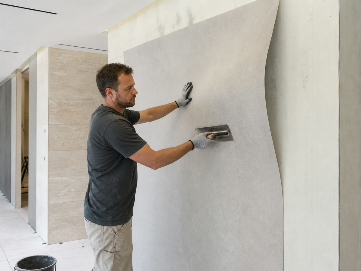
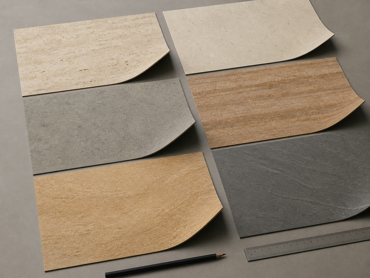
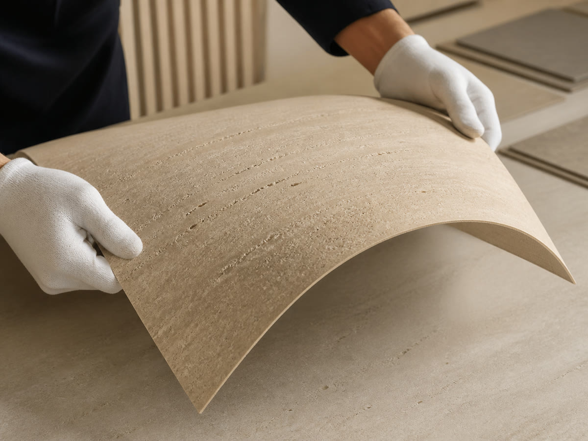
Use these visual references when reviewing the mock-up and work method with the project team.
Site checklist
1. Identify Panel Backing Class & Select Approved Blade (`EN 13236`)
Check the SKU datasheet in the flexible stone catalog and Composition & Backing to distinguish fiberglass-polyester natural stone (1.5-3.0 mm) from breathable MCM/fleece sheets (1.5-2.5 mm).
Engineering Rule of Thumb: Never use an alternating-top-bevel (ATB) wood saw blade (<= 24 teeth) or attempt a single-pass utility knife snap on fiberglass-backed natural slate or quartzite-wood teeth hook the woven fiberglass mat and rip 5-15 mm stone flakes off the face.
2. Verify Spindle RPM & Peripheral Speed (`40-63 m/s`)
Calculate blade peripheral speed V_c = (pi * D * N) / 60000 (EN 13236 / ANSI B7.1) before mounting any continuous-rim diamond blade (1.2-1.6 mm kerf).
Engineering Rule of Thumb: Keep diamond blade peripheral speed between 40 and 63 m/s (<= 9,625 RPM on a 125 mm angle grinder; never exceed the 80 m/s red safety ceiling). Running an unthrottled 11,500-13,000 RPM grinder dry raises kerf interface temperatures above 110-130°C, scorching the polyester resin into a black gummy smear and delaminating the stone edge.
3. Enforce `OSHA 1926.1153` Dust Control & Post-Wet-Cut Drying
Connect a full-capture dust shroud to a cyclonic HEPA extractor (>= 25 CFM per inch of blade diameter, 99.97% efficiency at 0.3 um) or use continuous water feed (>= 0.5 L/min) per OSHA 29 CFR 1926.1153 Table 1.
Engineering Rule of Thumb: If panels are cut on a wet bridge/tile saw, sponge off mineral slurry immediately and stack sheets vertically in a dry rack for 12-24 hours until backing moisture drops below 2.5% before applying 2-part EN 12004 R2T polyurethane or MS-polymer adhesive.
4. Pre-Drill Corner Relief Holes & Verify `NEC 314.20` Box Depth
Install listed electrical box extenders so box fronts sit <= 6 mm (1/4 in) back from the finished stone (NEC 314.20) and perimeter gaps remain <= 3 mm (1/8 in) (NEC 314.21).
Engineering Rule of Thumb: Before cutting any rectangular socket or access opening, drill a 6-10 mm (1/4-3/8 in) diamond hole at all four internal corners and keep at least 25-30 mm of uncut panel bridge to the nearest sheet edge-never cross-over straight saw cuts at 90° corners.
Key steps
Step 1: Benchmark the Wall Grid, MEP Coordinates & Joint Allowances
Snap chalk/laser control lines on the prepared substrate per Flexible Stone Installation and measure actual as-built coordinates for door casings, window reveals,
TCNA EJ171movement joints (2-3 mminterior /3-6 mmexterior), pipes, and electrical boxes. Verify all electrical boxes are fitted with listed box extenders so the box opening sits<= 6 mm (1/4 in)back from the finished stone plane (NEC 314.20).Step 2: Support on a Sacrificial Spoilboard & Mark with Low-Tack Tape
Lay the acclimatized sheet fully flat on a clean
18 mmMDF or high-density XPS foam spoilboard workbench. Apply blue low-tack painter’s masking tape along the cut path (on the fiberglass backside for straight power-saw cuts, or on the stone face for core drilling and3-passMCM utility scoring) and mark dimensions with a0.5 mmmechanical pencil or silver layout marker-never use permanent ink pens directly on porous travertine, sandstone, or limestone.Step 3: Execute Trial Cut at `40-63 m/s` with `OSHA 1926.1153` Dust Control
Clamp an aluminum straightedge guide rail across the panel, verify diamond blade peripheral speed is
40-63 m/s(EN 13236), and activate either continuous water feed (>= 0.5 L/min) or a shrouded HEPA H13/H14 vacuum (>= 25 CFM/inblade diameter). Trial-cut one spare offcut first, inspect the stone arris and fiberglass backing under grazing light, and send a labelled photo of the trial edge plus your cut schedule via Get a Quote or WhatsApp if you want engineering sign-off. We reply within 24 hours.Step 4: Deburr with `80-120 Grit`, Dry Wet-Cut Sheets & Seal Exposed Edges
Dress every cut edge with an
80-120 gritdiamond hand-rubbing block held at a45°micro-chamfer (0.3-0.5 mm) using unidirectional strokes from the stone face toward the backing to remove any fiberglass whiskers. If wet sawing was used, wipe slurry immediately and dry panels12-24 hoursto< 2.5%moisture before bonding. Dry-fit the cut panel against Corners & Edges and Joints & Sealing details before spreading adhesive.
Diamond Blade Kinematics (`EN 13236` / `ANSI B7.1`) & `OSHA 1926.1153` Silica Dust Extraction Matrix
Cutting natural stone veneers backed with unsaturated polyester resin and E-glass fibers generates two simultaneous hazards: thermal resin degradation inside the cut kerf if blade peripheral speed is too high, and airborne respirable crystalline silica (SiO2) + glass microfiber dust (OSHA 29 CFR 1926.1153 8-hour TWA Permissible Exposure Limit PEL = 50 ug/m3; Action Level AL = 25 ug/m3). Calibrate every shop and field saw against this engineering matrix:
| Blade / Tool Diameter & Configuration | Optimal Spindle RPM (40-63 m/s Window) |
Absolute Max Safe RPM (80 m/s EN 13236 Ceiling) |
Mandatory OSHA 1926.1153 Table 1 Dust / Coolant Control |
Dominant Machining Failure Mode & Prevention |
|---|---|---|---|---|
115 mm (4.5 in) Continuous-Rim Diamond Blade (1.2-1.4 mm kerf) on Variable-Speed Grinder |
6,640 - 10,460 RPM (set speed dial to Stage 3-4) |
13,280 RPM (EN 13236 red stripe limit) |
Full-capture plunge shroud + >= 115 CFM (3.25 m³/min) HEPA H13/H14 vacuum (>= 25 CFM/in), or wet feed >= 0.5 L/min |
Polyester resin scorching (> 120°C) & stone edge chipping -> Never run a fixed 12,000+ RPM grinder dry without a guide rail; throttle down to 8,000-10,000 RPM |
125 mm (5.0 in) Continuous-Rim Diamond or Fine Carbide Grit Blade (1.2-1.6 mm kerf) |
6,110 - 9,625 RPM (ideal for track-guided dry or wet cuts) |
12,220 RPM (ANSI B7.1 / EN 13236 max) |
Shrouded dust collector >= 125 CFM (3.54 m³/min) with cyclonic pre-separator + 99.97% HEPA filter, or wet spray |
Diamond rim glazing & blade core wobble -> Dress glazed diamond rim in an alumina dressing stick every 30-50 linear meters; verify 22.23 mm arbor flange clamp |
160-180 mm (6.5-7.0 in) Track-Guided Plunge Saw (1.6-2.0 mm Diamond or 48-60T TCG Carbide) |
4,240 - 6,685 RPM (at D = 180 mm) |
8,485 RPM (at D = 180 mm) |
Integrated plunge-saw extraction port + >= 175 CFM (4.95 m³/min) auto-pulse HEPA extractor on splinter-guard rail |
Splintered top stone veneer & fiberglass pull-out -> Cut with stone face pressed against sacrificial MDF spoilboard (backside up) or keep rubber rail splinter-guard tight |
250 mm (10.0 in) Sliding Wet Bridge / Table Saw (1.6-2.2 mm Continuous-Rim Stone Blade) |
3,055 - 4,810 RPM (45° bevel capable for corner miters) |
6,110 RPM (stationary wet saw rated) |
Continuous dual-nozzle water flood >= 0.5-1.5 L/min directly into blade nip point + slurry settling basin |
Moisture-trapped adhesive blistering (> 2.5% moisture) -> Rinse mineral slurry off both faces immediately after cutting and rack-dry panels 12-24 h before bonding |
Manual Utility Knife (0.5-0.8 mm) & Compound Aviation Tin Snips (Offset Shears) |
0 RPM (Zero airborne dust generation) |
Manual hand feed (3-pass score on MCM; < 2.0 mm trim notches only) |
Zero respirable silica dust (OSHA 1926.1153 exempt when scored without power abrasion); wear cut-resistant ANSI A4 gloves |
Crushed stone edges & upward curling on > 2.0 mm fiberglass sheets -> Restrict tin snips to short concealed trim notches on thin sheets; dress edge with 100-grit diamond block |
Engineering Rule of Thumb: Under EN 13236 and ANSI B7.1, centrifugal tensile stress inside a spinning steel blade core increases with the square of peripheral velocity (sigma_c ~ V_c^2)-meaning overspeeding a 125 mm blade from 8,500 RPM (55.6 m/s) to 12,000 RPM (78.5 m/s) doubles core centrifugal stress and spikes frictional kerf heat above the 110-130°C glass-transition temperature of polyester resin.
Engineering Formulas: Blade Peripheral Speed, Strip Nesting Yield & 45° Miter Setback
Use these three closed-form engineering equations to calibrate saw spindle speed, calculate exact sheet quantities when ripping panels into linear plank strips or custom formats (see Custom-Size Cut Plan), and set 45° bevel stops for external corners:
1. Blade Peripheral Speed & Max RPM (EN 13236): V_c = (pi * D * N) / 60000 <==> N_max = (V_c * 60000) / (pi * D)
2. Linear Strip Nesting Yield & Gross Takeoff Area: N_strips = floor((W_sheet - 2 * b_trim + w_kerf) / (w_strip + w_kerf)) ; A_gross = A_net * (1 + f_kerf + f_layout)
3. Back-Bevel Corner Miter Setback: x_miter = (t_panel - t_land) * tan(theta_bevel)
Where:
V_c= blade peripheral speed (m/s, target40-63 m/s, max80 m/s);D= outer blade diameter (mm);N= spindle rotational speed (RPM)W_sheet= raw sheet width (600 mmor1200 mm);b_trim= factory edge squaring allowance (2-3 mmper side if required);w_strip= target finished plank width (mm);w_kerf= saw blade kerf width (1.4-2.0 mmfor diamond/carbide saw;0.0 mmfor zero-loss utility scoring)f_kerf = w_kerf / w_strip= cumulative sawdust kerf loss fraction;f_layout= perimeter/cutout offcut waste (0.08straight walls,0.12-0.15diagonal/chevron or heavy MEP walls)t_panel= local panel thickness at corner (1.5-3.0 mmflat sheet;3.0-5.0 mmon 3D textured profiles);t_land= unbroken stone nose land left at the outer corner (0.5-0.8 mmto prevent razor-edge chipping);theta_bevel= saw tilt angle (43°-44.5°from vertical for a90°outside corner with adhesive key space)
Worked Example 1: Angle Grinder RPM Calibration & OSHA 1926.1153 Vacuum Airflow Check
A field crew cuts 2.2 mm fiberglass-backed quartzite sheets using a D = 125 mm (4.92 in) continuous-rim diamond blade (w_kerf = 1.4 mm) on a variable-speed grinder (3,000-11,000 RPM dial):
- Target RPM at
V_c = 55 m/s(Mid-Optimal Window):N = (55 * 60000) / (3.1416 * 125) = 8,403 RPM(set variable dial to~8,400 RPM; stay below the63 m/sthermal limit of9,625 RPM). - Minimum Shrouded Vacuum Airflow (
OSHA 1926.1153 Table 1):Q_min = 25 CFM/in * 5.0 in = 125 CFM (3.54 m³/min = 59 L/s)through a>= 99.97%HEPA H13/H14 filter.
Worked Example 2: Ripping 1200 x 600 mm Panels into 148 mm Linear Strips + 45° Miter Setback
A lobby feature wall (A_net = 85 m²) specifies 1200 x 148 mm horizontal stone planks ripped from standard 1200 x 600 mm sheets (0.72 m²/sheet, t_panel = 2.5 mm) on a track saw (w_kerf = 1.6 mm, b_trim = 2.0 mm per edge):
- Usable Strips per
600 mmSheet Width:N_strips = floor((600 - 4.0 + 1.6) / (148 + 1.6)) = floor(597.6 / 149.6) = 3.997 -> 4 stripsof1200 x 148 mm(0.7104 m²net plank area per0.72 m²sheet;f_kerf = 1.33%). (Note: specifying150 mmstrips without accounting for the1.6 mmkerf yields only3 stripsper sheet and creates25%offcut waste!) - Outside Corner Miter Setback (
t_panel = 2.5 mm,t_land = 0.6 mm,theta_bevel = 43.5°):x_miter = (2.5 - 0.6) * tan(43.5°) = 1.9 * 0.949 = 1.80 mmback-bevel depth.
Engineering Rule of Thumb: When designing linear strip or ashlar plank patterns from 1200 x 600 mm or 2400 x 1200 mm master sheets, always subtract 2.0 mm per rip cut (w_kerf = 1.6 mm + 0.4 mm dressing allowance)-size modules to 148 mm, 198 mm, or 298 mm instead of nominal 150 / 200 / 300 mm so every sheet yields exact full divisions with zero narrow waste ribbons.
MEP Penetrations, Electrical Box Setbacks (`NEC 314.20 / 314.21`) & Corner Termination Matrix
Over 60% of cracked or rejected flexible stone panels occur at electrical sockets, plumbing stub-outs, access doors, and external wall corners where notches concentrate tensile stress or unextended electrical boxes violate fire codes. Coordinate every penetration and edge transition with Corners & Edges and Joints & Sealing using this engineering matrix:
| Penetration / Edge Detail | Code & Dimensional Tolerance Baseline | Machining & Drilling Sequence | Edge Dressing & Sealant Detail | Dominant Failure Mode & Engineering Prevention |
|---|---|---|---|---|
Circular Pipe, Valve & Conduit Holes (D = 20-110 mm) |
Hole diameter = D_pipe + 4 to 6 mm annular perimeter clearance (2-3 mm radial gap) |
Clamp sheet stone face up onto >= 12 mm sacrificial plywood; drill with continuous-rim diamond hole saw at 800-1,800 RPM (15° entry tilt, then vertical, zero hammer) |
Chamfer hole rim lightly with 100-grit diamond sponge; fill 2-3 mm annular gap with neutral ASTM C920 silicone under escutcheon |
Back-side fiberglass delamination & radial star cracking -> Never drill unsupported panels in mid-air or engage hammer-drill percussion; keep >= 25-30 mm bridge to sheet edge |
Rectangular Electrical Box & Access Cutouts (Single / Multi-Gang) |
Perimeter gap to box edge <= 3.0 mm (1/8 in) per NEC 314.21; fully covered by faceplate |
Step 1: Drill 6-10 mm diamond holes at all 4 internal corners from front. Step 2: Flip sheet and connect straight lines between holes from backside with 115 mm diamond wheel |
Deburr internal edges with 100-grit file; verify device yoke ears seat flat on stone face without bending |
Over-cut 90° corner notches propagating diagonal thermal cracks -> Never cross-over straight grinder cuts past the corner point; always terminate straight cuts inside pre-drilled 6-10 mm corner radii |
Electrical Box Depth Setback (NEC NFPA 70 314.20) |
Box front edge <= 6.0 mm (1/4 in) setback in noncombustible stone/drywall (0 mm flush on combustible wood/MDF) |
Add panel (1.5-3.0 mm) + collapsed adhesive (2.2-3.5 mm = 4.0-6.5 mm total build-up); install listed noncombustible box extender / mud ring before bonding |
Ensure extender sleeve forms a continuous enclosure around wiring; use longer #6-32 device screws |
Recessed combustible cavity hazard & loose floating receptacles -> Audit existing box depth during Existing Surfaces survey and fit box extenders whenever setback exceeds 6 mm |
External 90° Mitered Stone Corner (Butt Miter Return) |
43°-44.5° back-bevel leaving 0.5-1.0 mm unbroken stone nose land; joint width 1.0-1.5 mm |
Cut on rail-guided plunge saw or wet bridge saw clamped flat; dry-fit corner pair and dress bevel with 120-grit diamond block |
Fill rear miter V-cavity with stone-tinted epoxy or MS-polymer adhesive; tool micro-joint flush and seal | Wavy "zipper" corner line & chipped feather edge -> Never grind a 45° feather edge to 0.0 mm thickness freehand; retain a 0.5-1.0 mm stone land or wrap curved corners (R >= 150-300 mm) |
Metal L-Trim, J-Channel & Door Casing Termination |
1.5-2.0 mm expansion clearance inside trim pocket; 2-3 mm perimeter caulk joint at door frames (TCNA EJ171) |
Cut straight factory-quality edge from backside (<= +/- 0.5 mm straightness); dress with 120-grit diamond pad and pre-seal cut edge |
Bed anodized aluminum or 304/316 stainless trim leg into adhesive; isolate stone cut edge from rigid frame contact with ASTM C920 sealant |
Edge buckling or water wicking into raw cut fiberglass -> Never jam raw cut panel edges tight (0 mm gap) against door frames or floor slabs; pre-seal cut edges in wet/exterior zones |
Engineering Rule of Thumb: Whenever a socket or pipe cutout falls within 25 mm (1.0 in) of a panel edge, shift the wall layout grid by 50-100 mm during dry-lay planning so the penetration lands inside a solid panel body, or split the cutout cleanly across two abutting sheets-a narrow < 20 mm stone bridge almost always snaps during J-roller consolidation.
TCO Hidden-Cost Ledger & Cutting / Drilling Failure-Mode Matrix
Uncontrolled field cutting is the single largest driver of preventable panel waste, dust-contamination shutdowns, and rejected architectural handovers on commercial stone veneer projects. Compare the upfront engineering prevention cost against the total cost of ownership (TCO) rework multiplier across these five field failure scenarios and cross-reference Troubleshooting and Over-Tile Cost Scope:
| Field Machining Failure Scenario | Root Cause in Tooling / Site Execution | Upfront Engineering Prevention Baseline | Failure Rework TCO Impact (Scrap + Replacement + Downtime) |
|---|---|---|---|
| Cleavage Spalling & Fiberglass Fuzzing Along Seams | Cutting fiberglass-backed slate/quartzite from the front face or using a 24T wood circular blade |
Track saw with EN 13236 continuous-rim diamond blade (1.4 mm kerf) cutting from backside + 100-grit diamond edge block |
6x-10x blade cost: 15-25% of sheets scrapped from jagged seams; requires air-freighting replacement batch from same quarry lot |
| Polyester Resin Scorch & Black Edge Delamination | Running an unthrottled 12,000 RPM angle grinder dry (V_c > 75 m/s), heating cut kerf above 120°C |
Variable-speed grinder set to 8,000-9,500 RPM (45-60 m/s) or wet bridge saw (>= 0.5 L/min water feed) |
5x-8x cutting labor: burnt resin loses bond to stone border (3-8 mm peel zone); edges lift after 2-4 weeks under HVAC cycling |
| Diagonal Corner Cracks From Electrical Box Cutouts | Over-cutting 90° box corners with a circular disc and skipping 6-10 mm corner relief holes |
Pre-drilling 4 x 8 mm diamond corner relief holes + connecting straight backside cuts on sacrificial plywood |
8x-14x cutout labor: hairline stress cracks propagate 100-300 mm across installed sheets; requires electrician disconnect and full sheet tear-out |
| Silica / Fiberglass Dust Contamination & OSHA Stop-Work | Unshrouded dry grinding inside occupied hotels, offices, or retail fit-outs (> 50 ug/m3 OSHA 1926.1153 PEL) |
Shrouded plunge guard + >= 125-175 CFM HEPA H13/H14 extractor (99.97% filter) or dedicated wet-cut station |
12x-18x vacuum rental: fine silica/glass dust contaminates HVAC ducts and adjacent millwork; triggers safety stop-work and deep-cleaning claims |
| Post-Wet-Cut Adhesive Blistering & Uncured Pockets | Bonding wet-sawed panels immediately while fiberglass/fleece backing holds > 4-6% water |
Sponge-wiping slurry + 12-24 h vertical rack drying to < 2.5% moisture meter check before R2T / MS-polymer bonding |
10x-15x drying hold cost: trapped water foams 1-part/2-part polyurethane or blocks MS-polymer wet-out, forcing multi-panel demolition |
Engineering Rule of Thumb: For commercial projects requiring more than 150 linear meters of narrow plank rips, mitered column corners, or repetitive hospitality room kits, compare site cutting labor and 12-15% waste against factory CNC bridge-saw / waterjet pre-cutting via our Custom-Size Flexible Stone Cut Plan-factory pre-cutting typically holds +/- 0.5 mm dimensional accuracy and reduces site installation labor by 30-40%.
Details to Prepare for Cutting, Drilling & Custom Fabrication Review
Before starting production cuts on site or ordering factory cut-to-size panels, assemble the five engineering records listed in the What to send us table below and share them via Get a Quote, Request Samples, or the floating WhatsApp contact:
- Panel SKU, Sheet Format, Thickness & Backing Class: Specify the exact catalog code (
1200 x 600 mmor2400 x 1200 mm), nominal thickness (1.5-5.0 mm), and backing platform (fiberglass-polyester,breathable fleece, orMCM) so we confirm blade selection. - Dimensioned Wall Grid, MEP Cutouts &
NEC 314.20Setbacks: Provide a dimensioned PDF elevation showing strip module widths (w_strip), pipe hole diameters (20-110 mm), electrical box counts, and movement joints (TCNA EJ171). - Visible Corner Miter, Reveal & Termination Details: Indicate whether outside corners use
45°back-bevel miters (0.5-1.0 mmland), thermal curved wraps (R >= 150-300 mm), or aluminumL/J-trimprofiles per Corners & Edges. - Proposed Cutting/Drilling Equipment, Spindle RPM &
OSHA 1926.1153Setup: State your saw/grinder model, blade diameter (mm), spindle RPM (40-63 m/scheck), dust extraction (CFM+ HEPA class or wet feed), and attach labelled photos of your trial offcut edge. - Net Wall Area (
m²), Cut Schedule & Delivery Destination: Include net vs. gross takeoff area (m²accounting forw_kerfand layout waste), zone packing marks, and destination city/port. We review your package and reply within 24 hours.
Frequently asked questions
Can every flexible stone panel be cut with a utility knife or heavy-duty shears?
No. Utility knife score-and-snap (3 passes against a clamped aluminum straightedge with a 0.5-0.8 mm bimetal blade) works cleanly only on homogeneous Modified Mineral Composite (MCM) and breathable textile-fleece-backed sheets (1.5-2.5 mm). Natural split-stone veneers (slate, quartzite, sandstone, travertine, and marble) reinforced with unsaturated polyester resin and woven E-glass fiberglass (1.5-3.0 mm) rapidly dull steel knife blades and fracture unevenly if snapped; they must be cut from the backside using an EN 13236 / ANSI B7.1 continuous-rim diamond blade (1.2-1.6 mm kerf) or a 40-60 tooth TCG carbide circular saw blade at 40-63 m/s peripheral speed.
Should we cut flexible stone panels from the front stone face or from the fiberglass backside?
When using a handheld circular saw, track saw, or angle grinder with a continuous-rim diamond blade, cut from the fiberglass-polymer backside while the stone face rests flat on a clean sacrificial MDF or XPS foam spoilboard. Because a handheld circular blade exits upward toward the tool baseplate, cutting from the backside directs compressive shear from the stone layer into the fiberglass backing, preventing metamorphic slate or quartzite flakes from spalling off the visible edge. On a stationary overhead wet bridge saw (where blade rotation pushes downward into the table), cut with the stone face up against a zero-clearance spoilboard.
How do we cut clean circular pipe holes and rectangular electrical box openings without cracking the sheet?
Support the panel flat on a sacrificial >= 12 mm plywood board and keep all cutouts at least 25-30 mm (1.0-1.2 in) away from the nearest sheet edge. For circular pipes (D = 20-110 mm), drill from the stone face downward using a continuous-grit diamond hole saw (core bit) at 800-1,800 RPM with rotary motion only (never hammer impact), starting at a 15° angle before leveling vertical. For rectangular electrical sockets (NEC 314.21 gap <= 3 mm), first drill a 6-10 mm (1/4-3/8 in) diamond stress-relief hole at all four internal corners from the front, then flip the panel and connect the straight cuts between the holes from the backside so the blade never over-cuts a 90° notch.
Is wet sawing or dry cutting better for flexible stone panels, and how do we control silica and fiberglass dust?
Both methods are approved when engineered to OSHA 29 CFR 1926.1153 Table 1 (PEL <= 50 ug/m3). Dry cutting with a track saw or variable-speed grinder (40-63 m/s) connected to a full-capture shroud and cyclonic HEPA H13/H14 vacuum (>= 25 CFM per inch of blade diameter, e.g., >= 125 CFM for a 125 mm / 5 in blade) is preferred on interior fit-outs because panels remain bone-dry (< 1.0% moisture) for immediate bonding with MS-polymer or EN 12004 R2T polyurethane adhesive. Wet bridge sawing (>= 0.5 L/min water feed) produces the cleanest 45° corner miters and zero airborne dust, but requires wiping slurry immediately and rack-drying panels 12-24 hours until moisture drops below 2.5% before adhesive application.
How should visible cut edges and outside 90-degree corners be finished and sealed?
Every cut edge must be dressed with an 80-120 grit diamond hand-rubbing pad at a 45° micro-chamfer (0.3-0.5 mm), stroking from the stone face toward the backing to remove micro-burrs and glass fibers. For outside 90° corners, choose one of three details in Corners & Edges: (1) a 43°-44.5° back-bevel miter cut on a rail/bridge saw that leaves a 0.5-1.0 mm unbroken stone nose land and is filled with color-matched epoxy/MS-polymer, (2) a curved thermal wrap (R >= 150-300 mm after warming the backing to 50-60°C), or (3) an anodized aluminum or 304/316 stainless steel L-trim / J-channel with a 1.5-2.0 mm expansion clearance and breathable edge sealer per Joints & Sealing.
When should we order factory pre-cut flexible stone panels instead of cutting sheets on site?
Order factory CNC bridge-saw or waterjet cut-to-size panels (see Custom-Size Flexible Stone Cut Plan) whenever a project involves repetitive narrow linear strips (< 200 mm wide), geometric chevron/herringbone modules, pre-beveled 45° column miter returns, or multi-room hotel refurbishment kits where indoor noise and dust are restricted. Keep final perimeter scribe-cuts, out-of-plumb wall trims, and field-verified MEP socket cutouts on site so installers can accommodate ANSI A108.02 wall tolerances.
Continue planning
Use these related guides before fixing details or releasing material.
Follow the 7-step wall installation sequence
Integrate dry-lay sequencing, backside cutting, notched-trowel bedding, and J-roller consolidation on site.
Read moreDetail 45-degree miters, curves & edge trims
Compare mitered external corners, thermal bend wraps, and aluminum L/J-channel terminations before cutting.
Read moreSeal cut edges & movement joints (TCNA EJ171)
Protect dressed stone edges and perimeter service gaps with neutral-cure ASTM C920 sealants and breathable sealers.
Read moreMatch adhesive chemistry to panel backing
Verify post-cut moisture limits (< 2.5%) and collapsed adhesive bed thickness (2.2-3.5 mm) at door/socket frames.
Read moreCompare factory cut-to-size vs. site cutting
Evaluate CNC bridge-saw / waterjet pre-cutting for repetitive linear strips, complex geometry, and multi-room kits.
Read moreSubmit cut schedule & MEP elevation for review
Send your SKU, dimensioned wall drawing, kerf/waste takeoff, and tool plan for engineering review within 24 hours.
Read moreWhat to send us
Scroll the table horizontally to see all columns.
| Item | Why we need it | Example format |
|---|---|---|
| Panel SKU, sheet format, thickness and backing class | Match diamond blade, carbide saw or utility score method to composite backing | Product code, sheet size (1200x600 or 2400x1200 mm), thickness (mm) and backing type |
| Dimensioned wall grid, MEP cutouts and NEC 314.20 box setbacks | Coordinate strip nesting, hole-saw diameters (20-110 mm) and <= 6 mm box extender depth | Dimensioned PDF elevation showing sockets, pipes, access hatches and movement joints |
| Visible corner miter, reveal and termination details | Verify 45-degree back-bevel miter allowance, L-trim clearances and exposed edge sealing | Corner detail sketch, labelled edge photos and door/window frame clearance log |
| Proposed cutting/drilling tools, spindle RPM and OSHA 1926.1153 dust control | Confirm EN 13236 peripheral speed (40-63 m/s), offcut trial edge quality and HEPA extraction | Saw/grinder model, blade diameter (mm), spindle RPM and labelled offcut trial photos |
| Net wall area (m2), custom cut-to-size schedule and delivery destination | Compare site cutting vs factory pre-cutting takeoff, waste allowance and freight scope | Piece schedule with net/gross area (m2), zone marks and destination city/port |
We reply within 24 hours.
Send your project details