Stone Column Wrap and Curved Wall Layout: Seams & Mock-Up Checks
Updated
A closing seam in the wrong place can force a stone column wrap to be recut. For a stone column wrap or curved wall layout, measure the proposed cladding plane, divide its developed length into panel faces and joints, then check every seam and sheet direction in a full-size mock-up before releasing cuts.
For a circular column, start with circumference C = πD and count the closing joint. For an open curved wall, calculate the arc length and keep the two end details separate from internal seams. This guide provides provisional layout calculations and a mock-up record for dry interior decorative walls. Confirm the selected flexible-stone product, usable dimensions and permitted forming direction before treating any layout as a cutting instruction. Start with the curved walls and columns application review if you are still choosing the finish and wall assembly.
Record the geometry and usable sheet dimensions
Name the measurement plane on the drawing and use it throughout the calculation. A structural column diameter, a built-out substrate diameter and a finished face diameter describe different circumferences. Ask the installer and supplier to resolve the final fabrication allowance from the actual assembly and fitting method.
| Input or item | Value or source to record | Why it matters |
|---|---|---|
| Diameter or curve profile | Survey drawing, mm, with named measurement plane | Defines developed length |
| Clad height and wrap extent | Elevation; full ring or open arc | Defines courses and end details |
| Usable sheet width and height | Selected SKU confirmation, including trimming | Controls piece divisions |
| Joint and end details | Designer's approved details | Separates panel face from installed coverage |
| Sheet and texture directions | Two labelled arrows on each piece | Prevents an unapproved rotation |
The size and thickness guidance distinguishes nominal dimensions from actual coverage. Treat 600 × 1200 mm and 1200 × 2400 mm as the two planning rectangles compared below, subject to confirmation for your selected SKU. A format name alone establishes neither a workable curve nor an available finished cut size.
Divide a circular column and count the closing joint
A closed ring of n pieces contains n joints, including the seam where the last piece meets the first. For equal panel faces and equal joints at the chosen layout plane:
C = πD
w = (C − n × j) ÷ n
Here D is diameter, C is circumference, n is the piece count per ring, j is the assumed joint width and w is each developed panel-face width, all lengths in millimetres. The joint width must come from the selected system and project detail; it is an input to the layout.
Worked example with assumed inputs: D = 600 mm, n = 4 and j = 3 mm gives C = π × 600 = 1884.96 mm and w = (1884.96 − 4 × 3) ÷ 4 = 468.24 mm. Check: 4 × 468.24 + 4 × 3 = 1884.96 mm after rounding. The 3 mm gap is an arithmetic assumption, not a recommended joint. These are developed face dimensions at the assumed plane; kerf, trimming, thickness effects and final fitting remain separate.
For that same hypothetical column, compare the following orientations. Each row assumes the stated nominal wrap dimension is fully usable; actual usable dimensions may reduce it.
| Planning rectangle and orientation | Pieces / joints per ring | Calculated face width | Dominant failure mode & prevention |
|---|---|---|---|
| 600 × 1200 mm; 600 mm around the column | 4 / 4 | 468.24 mm | Four seams become visible around the ring; locate all four on plan before cutting |
| 1200 × 2400 mm; 1200 mm around the column | 2 / 2 | 939.48 mm | An opposing seam is forgotten; review both approach views and the actual full-size sheet |
| 1200 × 2400 mm rotated; 2400 mm around the column | 1 / 1 | 1881.96 mm | Rotation changes face direction and handling; confirm the exact orientation and full-wrap feasibility |
Layout rule: if calculated w exceeds confirmed usable width U, increase the piece count or revise the format. A geometric fit where w ≤ U still requires the product-specific curve and installation check. Resolve vertical courses separately: for q courses, installed height includes q face heights, q − 1 horizontal joints and the top/base allowances. Sheet height alone cannot settle that layout.
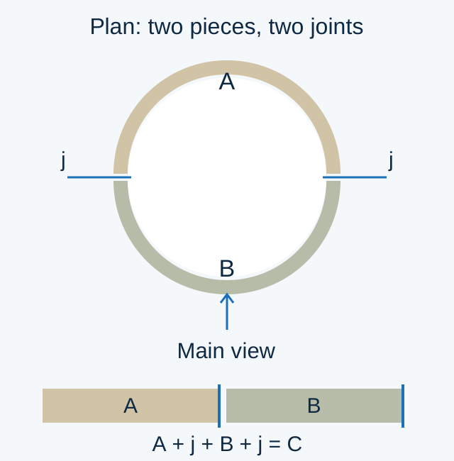
Two-piece planning schematic, not to scale. Both side joints remain part of the ring; the closing joint also appears in the developed-length check. Colours distinguish pieces A and B, not different finishes.
Lay out an open curved wall and a square-to-round build-out
An open arc has two ends and n − 1 internal joints. For a constant-radius wall, use the arc length rather than the straight chord between its endpoints:
L = π × R × θ ÷ 180
w = [L − e₁ − e₂ − (n − 1) × j] ÷ n
R is radius at the named layout plane, θ is the included angle in degrees, L is developed arc length, and e₁/e₂ are the approved end allowances. Assumed example: R = 1500 mm and θ = 90° give L = 2356.19 mm. With two equal faces, one 3 mm internal joint and two 5 mm end allowances, w = (2356.19 − 5 − 5 − 3) ÷ 2 = 1171.60 mm, rounded. These joint and end values illustrate the calculation only.
For a changing-radius curved accent wall, obtain the actual developed profile from the coordinated survey/drawing instead of assigning one radius to the whole wall. Mark transitions to straight walls, joinery and openings before dividing the run.
For a square column enclosed by a round build-out, measure the completed receiving profile. The original square perimeter does not define the new circular wrap. If the build-out retains flat faces and rounded corners, develop those portions separately and reconcile them with a full-size template. Coordinate the support, returns and movement details through the corners and edges review; a decorative sheet does not define the supporting construction.
Place every seam against sightlines and texture direction
Mark the main approach, side approaches and grazing-light direction on the column plan. Start by testing the closing seam in a less prominent viewing zone, then rotate the whole seam layout and check the other joints. On an equal two-piece ring the joints oppose each other; moving one to the rear puts the other towards the front. A column visible from all sides may have no hidden seam zone.
Carry piece IDs from the plan to the unwrapped elevation. Show top/base edges, horizontal joints and any adjacent flat wall. Keep intentional building movement joints distinct from appearance seams; use the approved wall-system detail wherever they intersect the cladding.
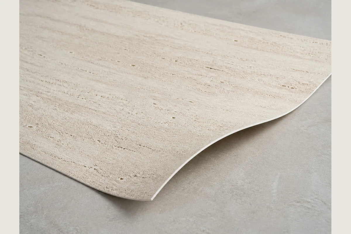
A linear face pattern gives the layout a visible direction. This material appearance reference does not establish a permitted bending axis or radius.
Draw one arrow for the sheet's long edge and another for the visible grain or relief. Identify the intended bend relative to both. Compare proposed along-grain and across-grain orientations using separately labelled samples and the selected product instructions. Confirm which orientation is permitted before forming; rotating a sample changes the proposal. Agree any heating, conditioning or restraint method with the product supplier and installer rather than borrowing instructions for another material.
Record the full-size mock-up and edge response
Use the proposed curve, product/backing, receiving surface, preparation, adhesive and joint/edge details together. Include the closing seam or an open-arc end, plus a representative horizontal joint if the elevation has one. Review the face and seams under the intended lighting. A small colour swatch can settle appearance; the full-size assembly checks the layout and installation proposal.
Use the following blank record for each proposed orientation. The responsible project team sets acceptance criteria and inspection timing from the selected system instructions, including when temporary restraint may be removed.
| Record field | Enter for this mock-up | Review / action |
|---|---|---|
| Product and direction | SKU, sample/batch reference, sheet-edge and face arrows: ___ | Match the proposed order and drawing revision |
| Geometry and pieces | Measured plane, diameter/profile, piece IDs and seam positions: ___ | Reconcile plan, elevation and actual fitting |
| Assembly and timing | Substrate, preparation, adhesive/primer, conditions and inspection times: ___ | Match the documented installation proposal |
| Face and seams | Photos of pattern continuity, face condition, joint and edge alignment: ___ | Record cracks, creases, backing separation or visible steps for review |
| Edge return / springback | Edge position before and after permitted restraint removal, with times/photos: ___ | Hold release if an edge lifts, the seam changes or the profile is not retained |
| Decision | Accepted revision / changes required / reviewer and date: ___ | Recheck affected details before issuing cuts |
Treat springback as an observation of the actual assembly after the agreed restraint sequence, not as a category-wide material rating. Do not force a failed sample into the proposed detail. Revise the product, curve, orientation or seam arrangement and repeat the affected check. Keep bonding questions with the adhesive and substrate review. Fire requirements and any exterior use need evidence for the exact product and complete application, separate from this layout record.
Compare the same scope before releasing the order
Compare alternatives through the same stage, from survey to accepted wall handover. Fewer joints can change cutting, handling and mock-up work; they do not establish a lower installed cost.
| Cost item | Record for each layout option |
|---|---|
| Material and offcuts | Confirmed supply pieces, usable dimensions, allocated remnants and separate spares |
| Fabrication and installation | Survey, cutting, edge work, handling and fitting responsibilities |
| Mock-up and revision | Sample material, preparation, labour and repeat work actually required |
| Completion | Protection, inspection and any agreed correction work before handover |
For a worked quantity check only, assume a ring/course uses four rectangular stock pieces of 600 × 1200 mm and four finished faces of 468.24 × 1200 mm. Stock area = 4 × 0.6 × 1.2 = 2.880 m²; face area = 4 × 0.46824 × 1.2 = 2.248 m². The difference is 0.632 m² before kerf and trimming; count reuse only after a remnant fits a named piece with the correct direction. This width-only example excludes horizontal joints and top/base details. It predicts no project waste percentage or price saving.
Transfer the approved piece IDs into the cut schedule and packing brief. Keep one revision for the survey, seam plan, mock-up decision and requested supply dimensions.
What to send us
| Item | Why we need it | Example format |
|---|---|---|
| Selected finish and sample | Identify the material under discussion | Product reference and sample photo |
| Measured curve and clad height | Describe the proposed wall | Dimensioned plan/profile and elevation with units |
| Seam layout and direction | Identify requested pieces and appearance | Piece IDs, joint/end references and two direction arrows |
| Receiving surface and mock-up record | Explain the installation proposal and unresolved items | Substrate photos, proposed materials and dated observations |
| Quantity and destination | Define the quotation scope | Piece schedule and city/country or port |
Request finish samples to compare the appearance, or send the drawing and piece schedule for a project quotation. Ask for the usable size and curve/direction information for the selected product before releasing the cutting layout.
Method and sources
Updated 19 October 2026. The formulas are geometric layout calculations with explicitly assumed inputs. HeyMaterials' published measurement, sample and project-review scope was checked on this date through the linked technical, application and enquiry pages. The material is flexible decorative wall cladding; the search term “column stone veneer” does not make it quarried natural stone.
For sealed joints, ASTM C1193-25, Standard Guide for Use of Joint Sealants, public scope and sections 4.1–4.2, describes joint materials, design and installation considerations and directs users to the sealant manufacturer for product use. That public guidance supports a system-specific joint review; it supplies no flexible-stone gap, bend limit or product approval. Final joint, forming and bonding details follow the selected system and project requirements.
What to send us
Scroll the table horizontally to see all columns.
| Item | Why we need it | Example format |
|---|---|---|
| Finish or product reference | Identify the sample or product to quote | Product link or reference photo |
| Wall area and quantity | Define the quotation scope | Dimensioned drawing or quantity schedule |
| Application and substrate | Understand the proposed wall | Wall photos and substrate description |
| Destination | Discuss packing and shipping | City and country or port |
We reply within 24 hours.
Send your project details